
How to Select a Mechanical Seal for a Mixing Tank? Single or Double Seal by Speed, Medium and Cleanliness
10/28/2026
Why Does a Mixing Tank Use a Mechanical Seal?
Bottom line: a mechanical seal closes the gap between the agitator shaft and the vessel with an end-face friction pair; leakage is small and life is long, making it the standard configuration for mixing tanks in clean, pressurized and flammable duties.
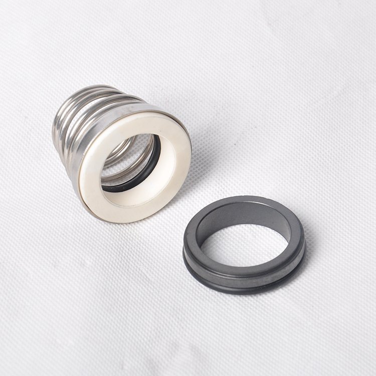
The agitator shaft enters the vessel through the top, and the gap between the shaft and the vessel is the main leakage channel. The old-style packing seal squeezes packing rings around the shaft: simple and cheap, but friction wear exists between the shaft and the packing, adjustment is needed during operation, leakage and dripping persist, and packing fibers can enter the product. A mechanical seal uses a pair of high-hardness end faces (rotating and stationary rings) pressed together by springs and medium pressure; a very thin liquid film forms between the faces, leakage is far smaller than a packing seal, and shaft wear is basically eliminated. In practice, mechanical seals have become the standard for clean, pressurized, vacuum, flammable and high-speed stirring duties; packing seals remain only for simple stirring at low speed, atmospheric pressure and no cleanliness requirement.
How Are Single and Double Mechanical Seals Selected?
Bottom line: general media use a single seal; flammable, toxic, easily crystallizing or zero-leakage-tolerance duties use a double seal, which places a barrier fluid or nitrogen between the two sealing stages.
A single mechanical seal has one friction pair: simple structure, low cost and easy maintenance, suitable for water, general liquids and ordinary chemical media, and it is the most common configuration for mixing tanks. A double mechanical seal has two friction pairs, and the cavity between them is fed with barrier fluid (seal oil or water) or pressurized nitrogen; even if the inner face fails, the medium cannot leak directly to the atmosphere. It suits flammable solvents, toxic materials, easily crystallizing materials, and food and pharmaceutical clean duties. The selection judgment can be simplified to three questions: is the medium flammable or explosive, is it toxic or strongly corrosive, and would leakage cause serious consequences; if any is yes, give priority to a double seal with flushing.
| Item | Single seal | Double seal |
|---|---|---|
| Friction pairs | 1 | 2 (barrier fluid between) |
| Suitable media | Water, general liquids, ordinary chemicals | Flammable, toxic, crystallizing, high cleanliness |
| Cost and maintenance | Low, simple | High, needs barrier-fluid system |
| Leakage risk | Inner-face failure leaks outward | Inner-face failure still isolated by barrier fluid |
How Are Seal Materials Determined?
Bottom line: the friction pair is generally silicon carbide against silicon carbide or silicon carbide against graphite; O-rings are FKM, EPDM or PTFE by medium; material follows medium corrosivity and temperature.
The friction-pair material determines wear resistance and dry-running resistance. The most common in practice is silicon carbide against silicon carbide: high hardness, wear-resistant, suitable for media with particles and frequent start-stop. Silicon carbide against tungsten carbide suits strong abrasive media with a longer life but higher cost; graphite against silicon carbide has good self-lubrication, suitable for high speed and possible brief dry running. Secondary sealing elements (O-rings, gaskets) are selected by medium: FKM for mineral oil and general solvents, EPDM for hot water, steam and strong alkali, PTFE-coated for strong acids and a wide temperature range. When the medium temperature exceeds 120℃ or strongly corrosive components are present, the whole seal-material scheme must be re-checked, not just the O-rings.
How Does Speed and Linear Velocity Affect the Seal?
Bottom line: the linear velocity of the seal faces determines heat generation; the higher the speed, the better the friction-pair material and flushing needed. Ordinary mixing tanks have moderate face speed; the key is controlling vibration and runout.
The relative sliding of the seal faces generates frictional heat, and the higher the linear velocity, the greater the heat. High-speed dispersing and emulsifying equipment can reach thousands of revolutions per minute, so the face speed is high and needs high-thermal-conductivity materials such as silicon carbide plus flushing to carry the heat away. The agitator shaft of an ordinary mixing tank generally runs in the range of tens to two hundred revolutions per minute, so the face speed is not high and heat is not the main issue; the key is to control the radial runout and vibration of the shaft. An over-long shaft, unbalanced impeller or improper baffle arrangement amplifies shaft deflection, causing long-term eccentric wear of the seal faces and sharply shortened life. When selecting the seal, the manufacturer therefore checks the shaft support, bearing span and critical speed together, rather than just the seal model. The agitation speed of a mixing tank matches the power and volume: the power density of a conventional tank is roughly 0.1 to 0.5 kW per cubic meter, and materials with higher viscosity go to the upper end. Once the speed is set, the seal-face linear velocity can be estimated from the shaft diameter and speed; the larger the shaft diameter, the higher the linear velocity at the same speed. In selection, give the manufacturer the three numbers of shaft diameter, speed and medium temperature together, so that the seal size and materials can be pinned down.
How Is the Flushing Plan Configured?
Bottom line: flushing cools the faces, carries away particles and maintains seal-chamber pressure; general duties use single-seal flushing, while hazardous and dirty media use double-seal pressurized flushing; the plan is selected per API flushing plans.
A mechanical seal needs flushing during operation: first to cool, carrying away the frictional heat of the faces; second to clean, preventing particle buildup on the faces; third to stabilize pressure, preventing the faces from separating due to pressure fluctuation. In practice, plans are often configured by the API 682 flushing-plan numbering: clean media use self-circulation flushing (Plan 11); media needing external clean liquid use external flushing (Plan 32); double seals are equipped with a barrier-fluid circulation system (Plan 53/54 class). For low-speed equipment like mixing tanks, a self-circulation flushing set suffices in simple duties; for double seals, the barrier-fluid system is supplied as a complete set by the manufacturer, and the site only needs to connect the piping and pressure gauge. The pressure, flow rate and temperature of the flushing fluid are written into the operating-parameter sheet, and operators patrol according to it.
How Does the Seal Cooperate with the Seal Chamber of a Mixing Tank?
Bottom line: the size, depth and shaft-diameter match of the seal chamber determine the seal installation space, and the relation between seal-chamber pressure and vessel pressure determines the flushing plan; design them together.
The seal chamber of a mixing tank generally consists of the top flange and the seal gland; the chamber depth must accommodate the spring compression and the flushing ports. When the vessel is under vacuum or slight positive pressure, the seal-chamber pressure is below atmospheric, the direction of the differential pressure across a single seal changes, and the flushing and barrier-fluid pressures must be re-checked for the vacuum duty. The larger the top stirring opening and the thicker the shaft, the higher the seal grade and the higher the cost; so first fix the shaft diameter, then the seal, not the other way around.
What Are the Installation and Acceptance Points?
Bottom line: installation checks perpendicularity and runout; acceptance does a static pressure test and idle run; shaft runout is generally controlled within 0.05 mm before installing the seal.
The seal is sensitive to shaft installation conditions. Before installation, check the shaft diameter and shoulder dimensions, and confirm that the runout and radial clearance are within the allowed range; in practice, the shaft runout at the seal location is generally required to be no more than 0.05 mm, and correction is needed first if it is not. During installation, align the compression amount and spring compression per the manufacturer's drawing, lubricate the faces, and tighten evenly in several passes. Acceptance has three steps: first a static pressure test, pressurizing the seal chamber to about 1.25 times the working pressure and observing for leakage; then an idle run, listening for abnormal noise and checking for temperature rise; finally a trial run with product, checking for dripping after continuous operation. A mechanical seal is a precision part: do not strike or press the faces during installation, and store it dust-free and moisture-proof.
How Are Routine Inspection and Faults Judged?
Bottom line: inspection looks at dripping, temperature rise and sound; face wear, insufficient barrier-fluid pressure and shaft deflection are the three main fault sources; for leakage, check the barrier-fluid system first before deciding to dismantle.
Routine inspection has three points. First, dripping: if the shaft seal area shows dripping, record the rate first, then judge whether it is seal failure or a system problem against the barrier-fluid pressure and flushing flow. Second, temperature rise: compare the seal area with the vessel temperature by hand or thermometer; abnormal heat is mostly insufficient flushing or dry running of the faces. Third, sound: sharp friction sound and periodic abnormal noise indicate face abnormality. For double-seal leakage, check the barrier-fluid pressure and level first; insufficient pressure causes the inner face to lose isolation. For single-seal leakage, first check whether flushing is interrupted. When dismantling, record the wear pattern of the faces: annular grooves indicate particle wear, cracks indicate thermal cracking, providing a basis for the next selection.
In real projects, seal selection is often decided together with the agitation form and tank opening: for the same 3000-liter mixing tank, ordinary liquid stirring only needs a single seal with self-circulation flushing, while solvent recovery or high-cleanliness formulations need a double seal with a barrier-fluid system, and the cost difference is obvious. Give the four numbers of medium, speed, temperature and pressure at once, and the manufacturer can match the seal, seal chamber and flushing plan in one pass. Spare seals are also stocked by the same model and material; with spare faces and O-rings, replacement does not wait for delivery. Once the seal runs stably, backfill the actual life and maintenance records into the equipment ledger, so that selection experience accumulates.
Summary
Mixing-tank mechanical-seal selection looks at three things: first determine single or double by medium, then determine materials by corrosion and temperature, finally determine flushing and shaft support by speed and vibration. Install with shaft runout corrected to specification, do static pressure and idle-run acceptance, and watch dripping and temperature rise in routine inspection; the seal will then run stably through its life. Our stainless steel mixing tanks are configured with single or double mechanical seals and flushing systems by duty; selection is welcome for discussion.
Related reading: - Why do reactor mechanical seals keep leaking? - How to select a stainless steel mixing tank?
This article is compiled by Hyline Stenda Equipment Manufacturing Co., Ltd. (hyline.cn), mainly supplying stainless steel reactors, mixing tanks, storage tanks, dispersers, concentrators and complete chemical line supporting equipment, with non-standard customization supported.
Q&A from this article
Frequently asked questions and answers from this article
Bottom line: the friction pair is generally silicon carbide against silicon carbide or sil…
Related Products
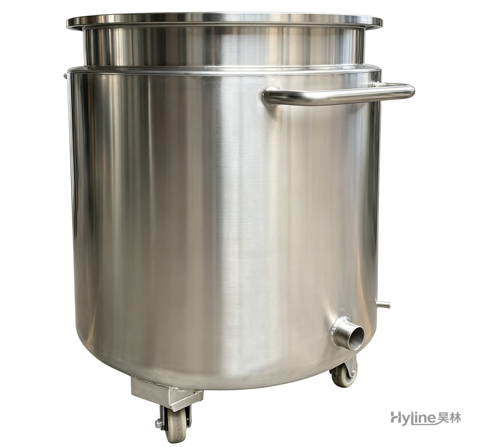
Stainless Steel Mixing Tank (Dispersion Drum)
Supporting vessel for dispersers and mixers in paints, coatings, adhesives, color slurries, inks and electronics. Available in 201/304 stainless with internal/external polishing and sloped bottom side discharge for complete draining.
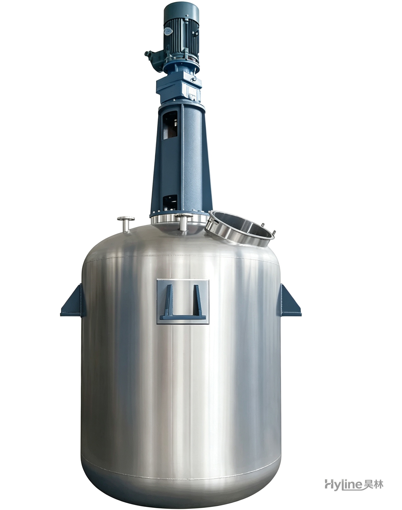
TC Series Mixing Kettle (Tinting)
For color matching in the paint industry and liquid-liquid / liquid-solid mixing in other industries. Uniform tinting, good miscibility, reasonable structure and powerful stirring.
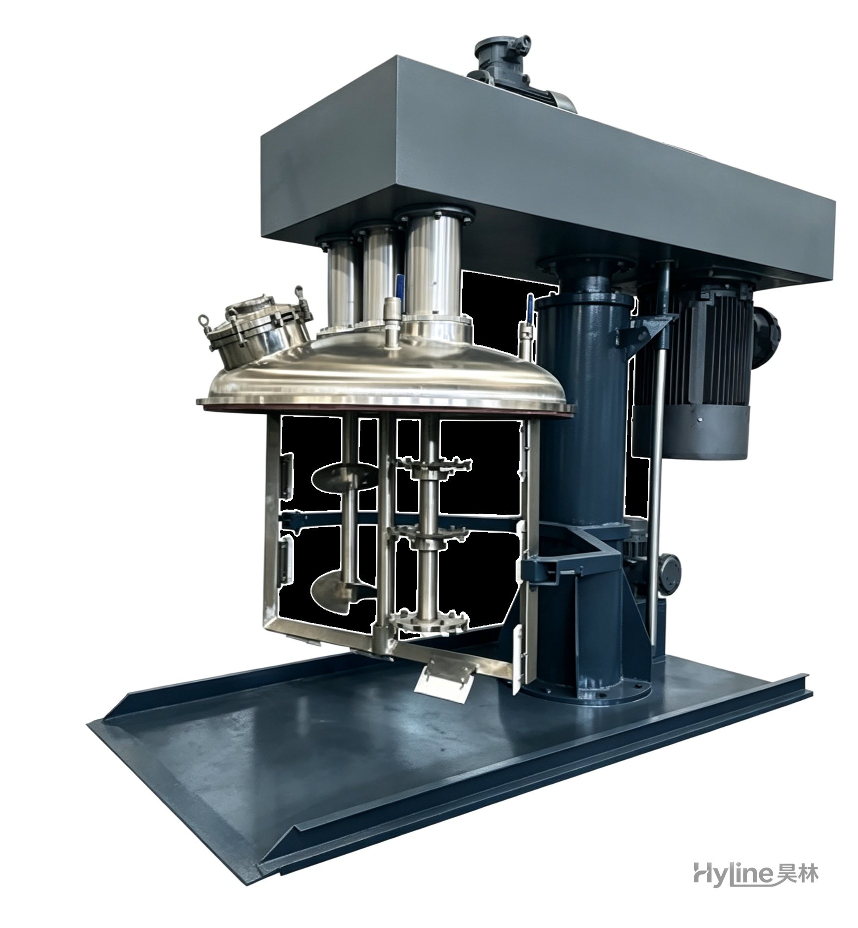
SJ Series Multi-Function Mixer
A new high-efficiency mixer for high-viscosity materials, rapidly dispersing, dissolving and homogenizing. Widely used in offset printing inks, putties and adhesives. Vacuum type customizable.
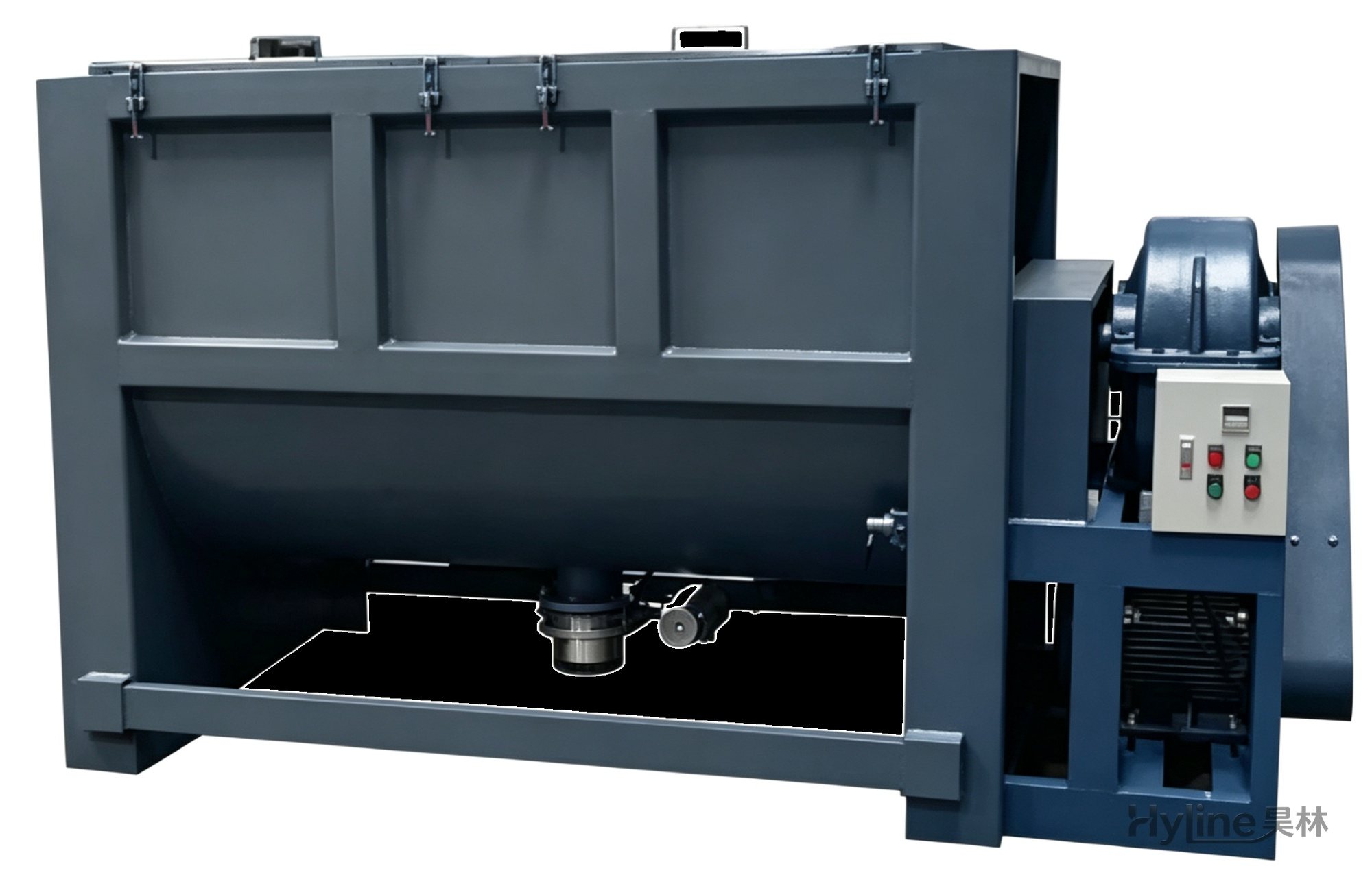
Horizontal Mixer
For color blending of plastic pellets, new/old materials and additives. Single-layer for mixing; double-layer with oil heating of 50-150℃ (custom up to 300℃). Ideal for PVC/PP/PE pellets and chemical powders such as calcium carbonate and titanium dioxide.