
How to arrange the nozzle of the mixing tank: key points for the design of the tank top connection and maintenance space
10/4/2026
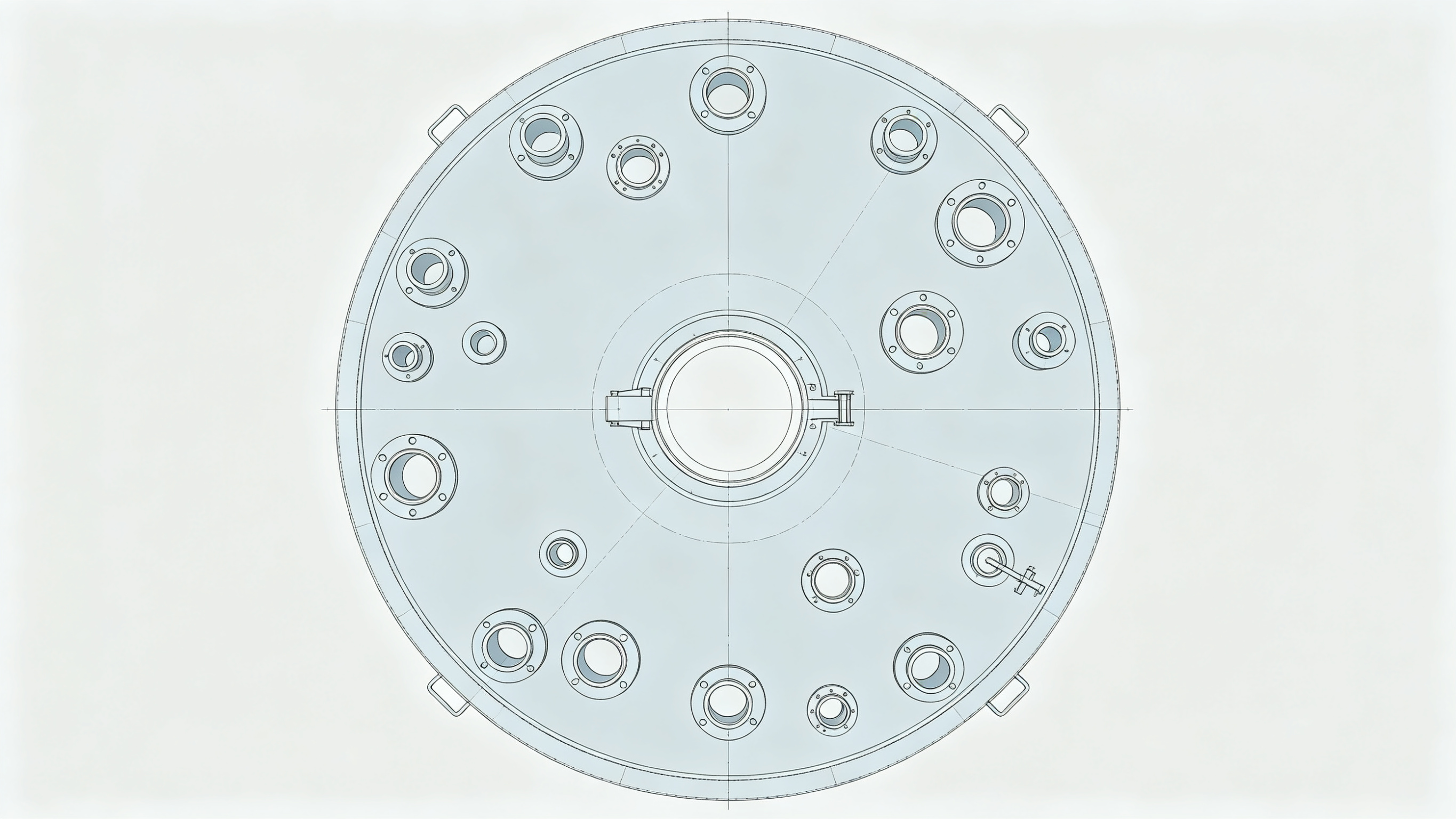
1、 Why is the arrangement of pipe openings important
The pipe openings of the mixing tank include feeding port, discharging port, exhaust port, temperature measuring port, liquid level port, manhole and sight glass port, etc., ranging from six or seven to more than ten. Reasonable arrangement of pipe openings, short and straight pipelines, convenient maintenance, and easy operation; If the layout is messy, pipelines will be bypassed, valves will not be accessible, and a large number of pipelines will need to be dismantled for maintenance. The position of the pipe opening affects the entire body: the pipe opening inside the tank affects the mixing flow field, and the pipe opening outside the tank affects the direction of the piping, which must be planned as a whole during the design phase.

2、 Classification of pipe openings by position
The pipe openings are divided into two types according to their positions: the top and the side of the tank, each with its own layout principles:
**Tank top pipe opening * *: including feeding port, exhaust port, temperature measuring port, sight glass and manhole, concentrated on the top of the tank for easy piping and operation, as well as convenient cleaning inside the tank. The layout principle is to concentrate as much as possible near the manhole to reduce back and forth movement during maintenance.
**Tank side pipe opening * *: including discharge port (usually located at the bottom or lower part of the tank), liquid level gauge port (located at the top and bottom of the tank side), and jacket inlet and outlet. The layout principle is to avoid the mixing blade and baffle area to prevent interference; The discharge port should be as low as possible to ensure thorough discharge.
After determining the position of the pipe mouth, plan the direction of the piping. First, determine the internal components and mixing flow field of the tank, then determine the position of the pipe mouth, and finally perform interference inspection.
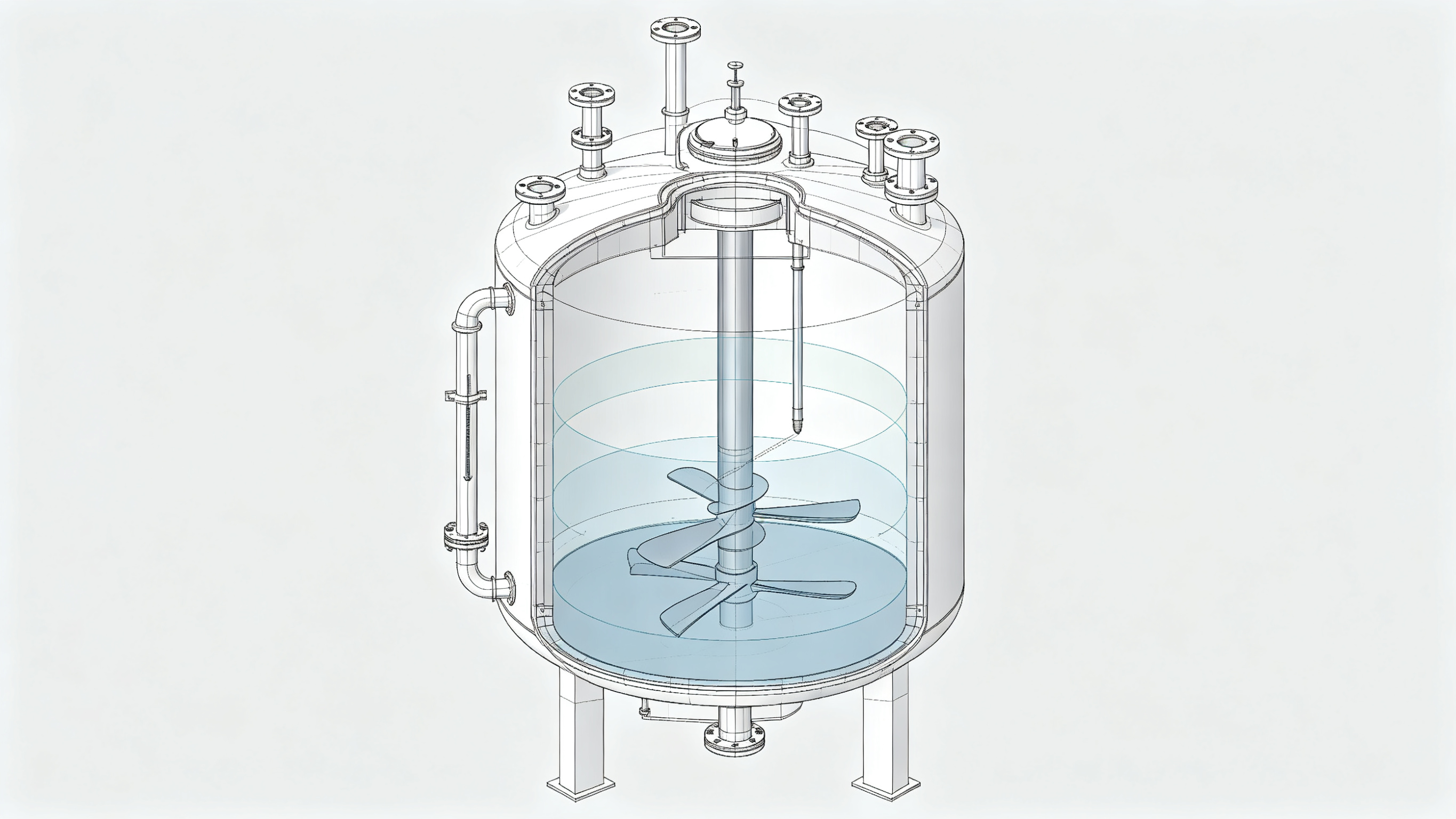
3、 The functions and layout points of common pipe openings
|Type of pipe mouth | Recommended location | Function | Layout points|| --- | --- | --- | --- ||Feed inlet | tank top | material input | gravity feeding leaving enough space above; Pump feed to avoid impacting the liquid level||Discharge port | bottom/side lower part of the tank | discharge material | try to be as low and centered as possible to ensure thorough discharge||Exhaust port | highest point of tank top | exhaust gas | pipe diameter selected according to breathing rate, equipped with dust cap or flame arrester||Temperature measuring port | Tank side/top | Measure material temperature | Insert depth to cover the main body of the material liquid, avoiding the inlet of the feed and steam||Liquid level port | Two locations on the tank side | Measuring liquid level | The upper port is above the highest liquid level and the lower port is below the lowest liquid level||Manhole | Center or side of tank roof | Maintenance channel inside the tank | Leave sufficient maintenance space around, and there should be no pipelines blocking above||Mirror mouth | Tank top/tank side | Observing the liquid | Avoiding the stirring impact zone, equipped with lighting interface|
4、 Details of the layout of the feed inlet
The position of the feed inlet depends on the feeding method:
-Gravity feeding: The feeding port is located at the top of the tank, with sufficient operating space above the pipe opening for manual or lifting feeding;-Pump feeding: The feeding port can be slightly offset, but avoid splashing caused by the impact of the feeding on the liquid surface;-Powder feeding: The feeding port is equipped with a dust removal interface or a vacuum suction port, considering the direction of the dust removal pipeline;-Multi stream feeding: Separate feeding ports for different materials to prevent cross contamination.
Cleaning should also be considered for the feed inlet: the feed pipe should be as short and straight as possible to avoid material residue; Using flanges or quick connectors for easy disassembly and cleaning.
5、 Priority guarantee of manhole and maintenance space
The manhole is the only access for maintenance inside the tank, and its layout should be prioritized. The manhole is located in the center or on the side of the tank top, and the size is selected according to the maintenance requirements: the diameter of the atmospheric tank is four to five hundred millimeters, and for tanks that require maintenance, it is selected to be over five hundred millimeters. Leave sufficient maintenance space around the manhole, and there should be no pipelines blocking it above. After opening, people can enter and exit directly up and down. It is not advisable to install baffles and paddles inside the tank directly below the manhole to avoid injury from entering and exiting. Other pipe openings on the top of the tank shall be arranged around the manhole, but shall not block the manhole operation area.
6、 Instrument nozzle and measurement accuracy
The position of the temperature measuring port and the liquid level port directly affects the measurement accuracy:
**Temperature measuring port * *: The insertion depth of the thermometer should cover the main body of the material and not stick to the tank wall, otherwise it will measure the wall temperature rather than the material temperature; Avoid feeding and steam inlets to prevent local temperature interference; The thermometer sleeve should consider stirring the flow field to avoid being interrupted by the blade.
**Liquid level port * *: The upper port is above the highest liquid level and the lower port is below the lowest liquid level, with the distance between the upper and lower ports covering the actual measurement range; Avoid the feed impact zone to prevent liquid level fluctuations from interfering with readings.
The reasonable position of the instrument pipe mouth is a prerequisite for reliable measurement data and should be determined together during the drawing stage.
7、 Exhaust and safety pipe openings
The exhaust port and safety pipe opening should not be taken lightly either:
1. The exhaust port is located at the highest point on the top of the tank to prevent gas accumulation in blind spots;2. The diameter of the pipe is selected according to the breathing rate, and the dust cap and flame arrester are determined according to the medium;3. The safety valve port is independently set and not shared with other pipe ports to ensure smooth pressure relief;4. The vacuum port and vent port of the vacuum operation tank should be separated to prevent mutual interference between pumping and draining;5. The nitrogen interface of the nitrogen sealed tank is equipped with a check valve to prevent the backflow of the liquid material.
The layout of safety pipe openings is clear, making operation and maintenance worry free. The arrangement of pressure bearing and safety accessories should also meet relevant regulatory requirements.
8、 Interference inspection between the pipe mouth inside the tank and the mixing process
The pipe mouth inside the tank and the mixing device must undergo interference inspection together:
-The length of manhole, sight glass, and temperature measuring sleeve inserted into the tank should be checked with the sweeping range of the blade to avoid the blade hitting the pipe mouth;-The position of the baffle and blade should avoid the liquid level port on the tank side;-The pipe mouth near the centerline of the mixing shaft should avoid interference with the shaft and coupling;-The high-pressure cleaning ball and spray device should cover the entire tank wall.
Interference inspection should be completed during the drawing stage, which is much more convenient than making changes after installation. The layout diagram of the internal components of the tank should be clearly drawn and labeled with complete dimensions, and the manufacturing drawing should be produced after item by item verification.
9、 Piping outside the tank and ease of operation
The piping outside the tank should also be coordinated with the position of the pipe opening to consider operational convenience:
1. Valves and instruments should be installed at a height within reach of the operator, and if they are too high, an operating platform should be provided;2. The orientation of the pipe mouth is convenient for connecting, and the flange bolts face outward for easy disassembly and assembly;3. Centralized layout of pipelines and unified support in the same area;4. The pipeline has a slope that can be emptied and fewer dead corners;5. For pipelines that require frequent disassembly during maintenance, quick connect fittings or flange connections should be used.
The layout of the discharge outlet at the bottom of the tank directly determines the thoroughness of the discharge: the central discharge at the bottom of the tank is the cleanest, but it needs to be coordinated with the mixing shaft and shaft seal; The discharge from the lower part of the tank should avoid the shaft area and the pipeline should be flexible, but there may be a small amount of residue at the bottom of the tank; The lowest point should be set at the discharge outlet of the conical or inclined bottom tank for the best emptying effect.
10、 Requirements for Cleanrooms and Food and Pharmaceutical Cans
Food, medicine, and clean room cans must have their pipe openings arranged to meet cleaning requirements
|Requirement item | Specific method|| --- | --- ||Inner surface | The inner surface of the pipe mouth is flush or smoothly transitioned with the tank body, leaving no dead corners or steps||Cleaning coverage | Cleaning ball and spray device cover all tank walls and top pipe openings||Sealing surface | Smooth and easy to clean sealing surface for manhole and observation port||Connection method | Use quick release clamps for pipeline connections||Welding quality | The welding seam inside the tank is polished smooth, and there are no dead corners at the welding point of the pipe mouth|
The number of pipe openings should be minimized as much as possible, and having one more pipe opening will result in one more hygiene risk point. The arrangement of pipe openings in the clean room should be considered in conjunction with the Process Cleaning Validation (CIP) scheme.
11、 Frequently Asked Questions and Answers
Question: Is it better to have more pipe openings? No, it's not. Each pipe opening is a leakage and hygiene risk point, sufficient is sufficient, and excess pipe openings should be eliminated or replaced with reserved blind flanges as much as possible.
Question: Should we first determine the pipe opening or the mixing process? It is recommended to first determine the internal components and mixing flow field of the tank, then determine the position of the pipe mouth, and finally perform interference inspection to avoid rework.
Q: How to solve the problem of uncleaned discharge port? Adopting a tank bottom central discharge or conical/inclined bottom tank, with the discharge outlet located at the lowest point; The discharge from the tank side can be diluted with a small amount of flushing.
Attachment: Pipe mouth dimensions and flange standards
After determining the number of pipe openings, the nominal size and connection standards of each pipe opening need to be determined according to the process conditions: the diameter of the inlet and outlet should be determined according to the maximum flow rate and velocity requirements, as excessive flow rate will exacerbate wear and splashing; The exhaust port is determined based on the maximum breathing rate, and when equipped with safety accessories, it is selected according to the medium and pressure level; The diameter of the instrument port matches the instrument interface; The pressure rating of the flange is selected based on the highest working pressure, taking into account thermal stress and sealing gasket material; Quick connect fittings are used in clean workshops, while flange connections are used for regular working conditions. The diameter of the pipe mouth and the flange standard should be determined at the drawing stage to avoid changing the mouth after manufacturing.
Attachment: Tank Top Platform and Operating Space
When there are many pipe openings on the tank top, the tank top operation platform should also be planned synchronously: the platform elevation should match the flange operation height of the tank top pipe opening, leaving enough space for valve and instrument operation; Platform guardrails shall be set up in accordance with safety regulations; A detachable cover plate is left on the platform above the manhole for easy lifting in and out. The unified design of the tank top platform and piping support can reduce the risk of high-altitude operations and improve maintenance efficiency.
Attachment: Pipe mouth number and identification
The pipe mouth number and identification cannot be ignored: the drawing and nameplate number correspond to the pipeline valve, and during maintenance, the pipe mouth should be found according to the number to reduce the risk of connecting the wrong pipeline. It is recommended to list a list of pipe openings on the tank nameplate, consistent with the PID diagram.
Attachment: Key points for installation acceptance
After the equipment arrives, check the number, position, and flange specifications of the pipe openings according to the drawings, inspect the sealing surface and inner wall polishing quality one by one, and then conduct piping and pressure tests. The list of pipe openings and PID diagram should be checked item by item to avoid rework due to misalignment of pipe openings in the later stage.
12、 Summary
The layout of the mixing tank pipe mouth is a homework that needs to be done well in the design stage. First, determine the internal components and mixing flow field of the tank, and then determine the position of the pipe mouth; Priority should be given to manholes to ensure maintenance access, instrument ports to ensure accurate measurement, and inlet and outlet ports to ensure thorough discharge of materials; Inspect the interference between the pipe mouth, mixing, and pipeline one by one; The clean room implements hygiene and cleaning requirements in place. The pipe mouth number and identification cannot be ignored. The drawing and nameplate number correspond to the pipeline valve. During maintenance, the pipe mouth should be found according to the number to reduce the risk of connecting the wrong pipeline. Haolin Shengda Equipment Manufacturing Co., Ltd. has been deeply involved in the design and manufacturing of mixing tanks for many years, and can provide overall solutions for tank and pipe layout for different working conditions.
Q&A from this article
Frequently asked questions and answers from this article
The layout of the mixing tank pipe mouth affects the convenience of piping, maintenance, and operation. This article provides design points from the aspects of tank top/side layout, manhole and maintenance space, instrument pipe mouth, pipe mouth and mixing interference inspection.
Related Products
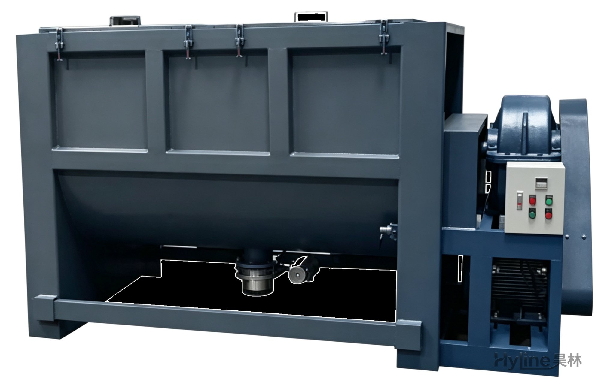
Horizontal Mixer
For color blending of plastic pellets, new/old materials and additives. Single-layer for mixing; double-layer with oil heating of 50-150℃ (custom up to 300℃). Ideal for PVC/PP/PE pellets and chemical powders such as calcium carbonate and titanium dioxide.
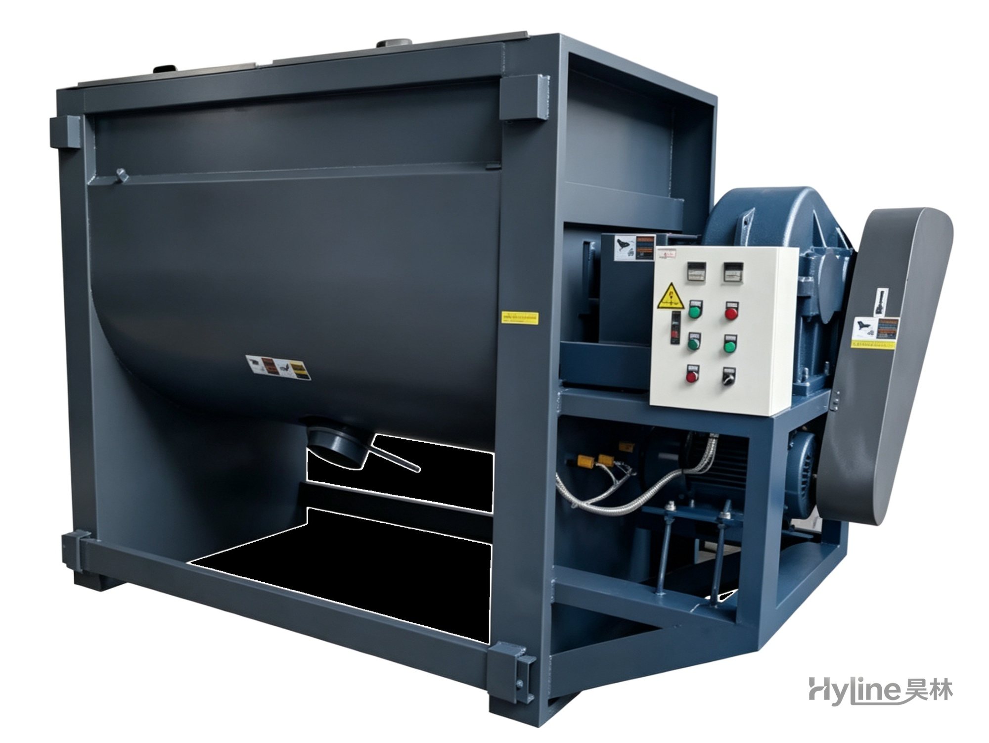
Horizontal Mixer (Heating Type)
Double-layer U-shaped stainless horizontal mixer with thermal oil heating of 50-150℃ (custom up to 300℃). S-shaped stainless blades for even mixing; dual mixing & drying functions with multiple safety protections.
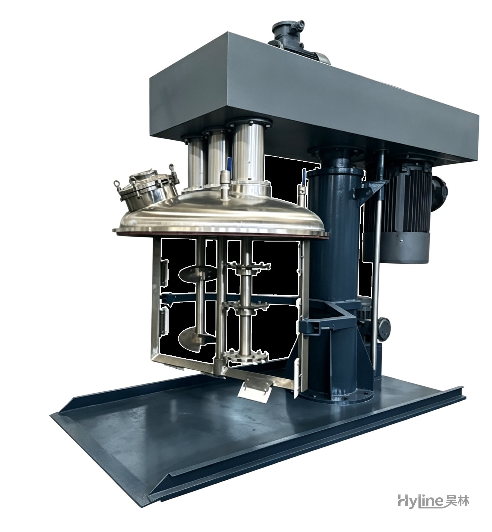
SJ Series Multi-Function Mixer
A new high-efficiency mixer for high-viscosity materials, rapidly dispersing, dissolving and homogenizing. Widely used in offset printing inks, putties and adhesives. Vacuum type customizable.
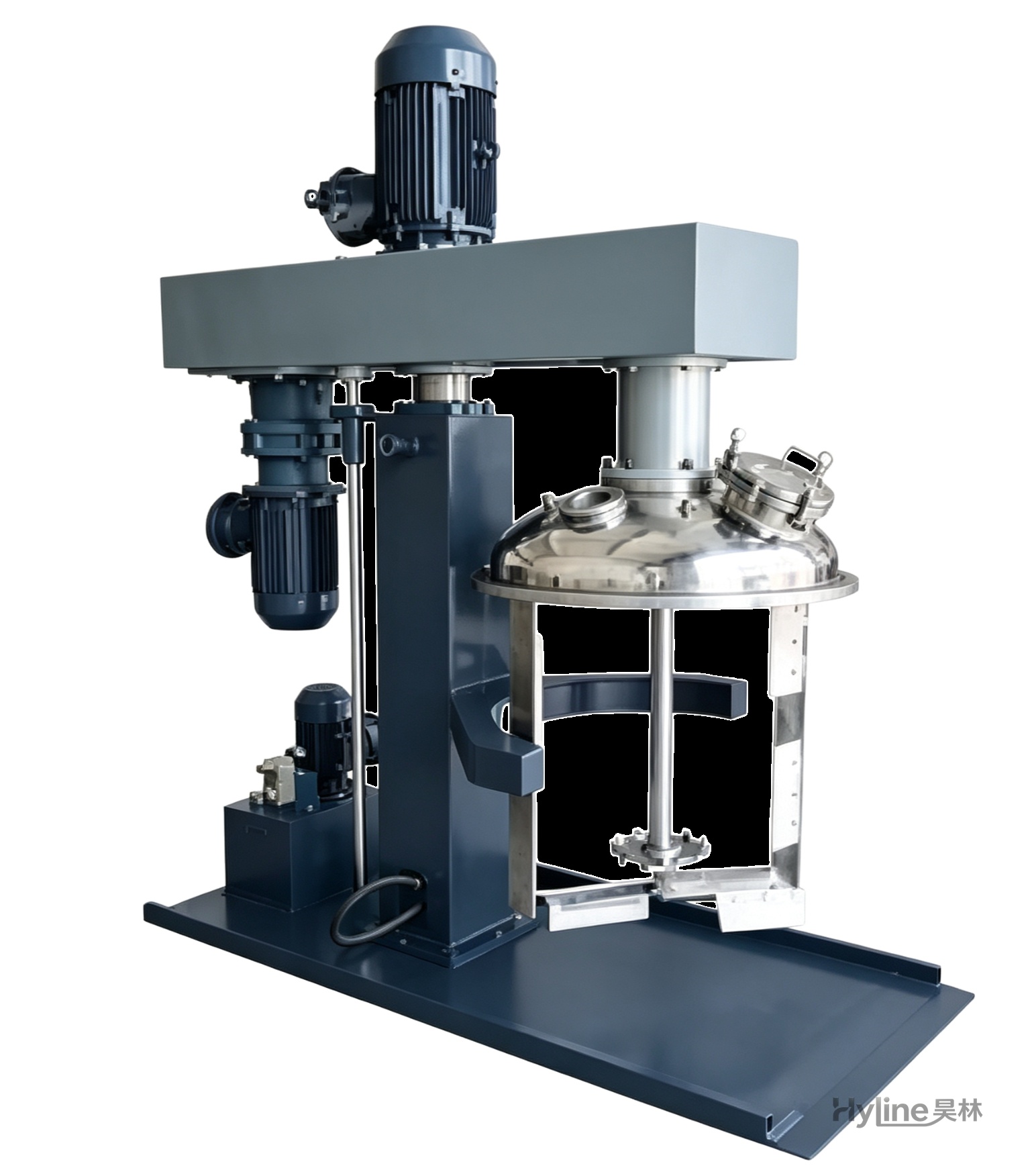
TSJ Series Concentric Twin-Shaft Mixer
Mixes materials of 3000-20000 cps. Low-speed blades with Teflon scrapers sweep the tank wall and push material to the center; high-speed toothed impellers disperse powerfully. High and low speeds run independently.
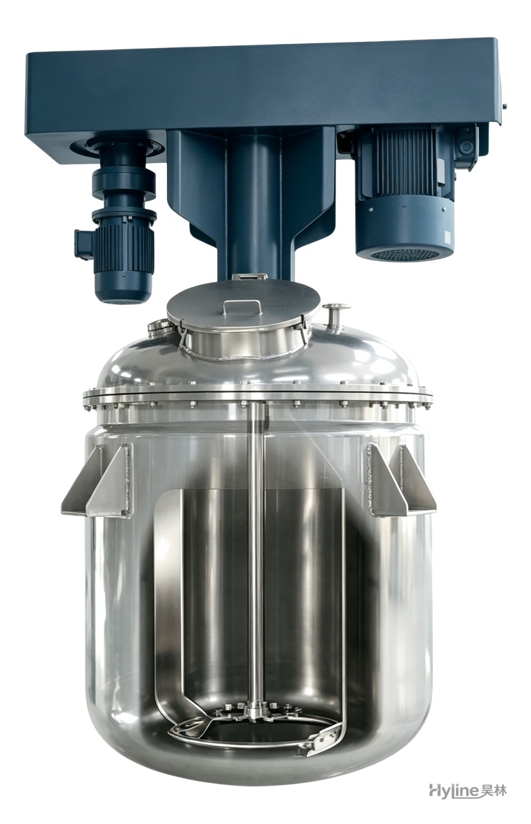
TSJ Concentric Twin-Shaft Platform Mixing Kettle
Platform-type concentric twin-shaft mixing kettle for 3000-20000 cps materials. Low-speed blades with Teflon scrapers eliminate dead zones; high-speed toothed impellers disperse powerfully. Supports large-volume batch production.
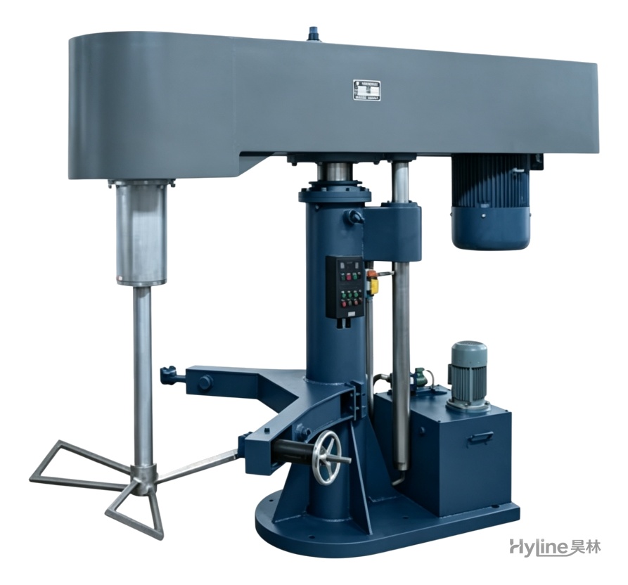
DSJ Series Butterfly Mixer
High-efficiency mixer with three-blade butterfly impellers. Vacuum during mixing improves quality; simultaneous mixing and automatic lifting boost productivity. For high-viscosity putty, adhesives and offset inks.