
How to Configure a Reactor Condenser? Reflux, Solvent Recovery and Tail-Gas Condensation Explained
11/7/2026
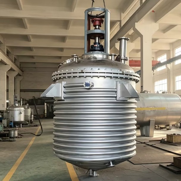
Why Does a Reactor Need a Condenser?
Bottom line: a condenser on a reactor is not an extra piece of equipment but a way to stop vaporized material from escaping - either refluxing it back to control temperature and composition, recovering it as solvent, or condensing the tail gas for treatment. All three duties share the same heat-transfer logic.
In esterification, polycondensation, solvent-based synthesis and distillation-concentration duty, some components of the charge always vaporize once the reactor heats up. If the vapor vents directly, costly solvent is lost and odorous material enters the workshop and atmosphere, which neither environmental compliance nor cost accounting tolerates. A condenser installed on the top vent line condenses the vapor - tube side for vapor, shell side for cooling water - and the condensate can be returned to the reactor, collected and metered, or routed to the tail-gas system depending on the process. This is why most reactor proposals list the condenser alongside the jacket as standard: the jacket manages heat going in, the condenser manages vapor going out, and together they determine reactor temperature and material routing.
For procurement purposes, the condenser involves heat-transfer area, type, mounting height and piping layout; changing it later affects everything, so it should be confirmed together with the reactor quotation rather than added after delivery.
What Problems Do Reflux, Recovery and Tail-Gas Condensation Solve?
Bottom line: reflux sends the condensate back into the reactor to hold temperature and carry away reaction heat; recovery collects the condensate as product or solvent; tail-gas condensation cleans up the small fraction that resists condensing. One condenser can serve all three duties, but piping and valves must be designed for the intended purpose.
Reflux condensation is common in exothermic and volatile systems. Reaction heat vaporizes light components, the condenser turns them back into liquid, and the liquid drains back into the reactor; the latent heat is carried away by cooling water, so the evaporation-condensation cycle helps the jacket share the cooling load. As long as the reactor temperature stays away from a runaway, this cycle holds the temperature more gently than simply increasing jacket cooling water. In esterification the duty is even clearer: water must be removed for the reaction to proceed, so a decanter follows the condenser - water phase out, organic phase back into the reactor.
Solvent recovery is typical of batch distillation and concentration. The condensate does not return; it is diverted to receivers and collected by fraction, forecuts and middle cuts separated, and with vacuum the same train performs low-temperature distillation. This mirrors the evaporation-condensation logic of a concentration vessel: vacuum lowers the boiling point, the evaporation chamber produces vapor, the condenser collects liquid - the difference is that a concentrator makes evaporation the main line while a reactor uses condensing as support. Tail-gas condensation sits at the end of the train and condenses the remaining condensable fraction, so downstream carbon adsorption or scrubbing is lighter and the stack easier to keep compliant.
How to Select the Condenser: Type, Area and Cooling Water?
Bottom line: vertical tubular and coil condensers are the most common for batch reactors; the area is estimated from vapor load with margin; summer cooling-water temperature and water quality set the long-term capacity. Fix all three together - never quote only one area figure.
A vertical tubular condenser mounts upright on the top vent line: vapor rises inside the tubes, condensate drains down the tube walls by gravity straight back into the reactor, and non-condensables vent from the top. It is compact and reflux-friendly, the first choice for batch duty. A horizontal tubular condenser gives a slightly higher heat-transfer coefficient and is easy to parallel for large recovery duty, but condensate removal depends on slope and the drain design. A coil condenser is simple and inexpensive, common on small reactors or low recovery duty, but the coil is hard to clean once the water side fouls.
Area is estimated from the vapor generation rate: convert the maximum hourly evaporation into a heat duty via latent heat, then divide by the heat-transfer coefficient at the condensing temperature difference. Batch duty fluctuates, so the area usually carries a 20%-50% margin over the calculation; for vacuum distillation, also account for the reduced coefficient as non-condensables increase. The table below compares the three common types:
| Condenser type | Typical mounting | Suitable duty | Features and cautions |
|---|---|---|---|
| Vertical tubular | Upright on top vent, reflux by gravity | Batch reflux, small-to-medium recovery | Smooth reflux, compact; condensate films back along tubes |
| Horizontal tubular | Horizontal on platform, sloped drain | Large recovery, multi-reactor sharing | Slightly higher coefficient; mind drain slope and venting |
| Coil | Upright or immersed | Small reactors, minor condensing | Simple and cheap; fouled coils are hard to clean |
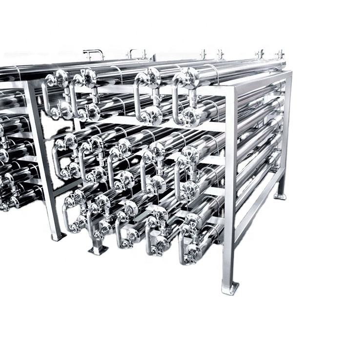
The cooling-water side is often underestimated. When summer loop temperature rises, the same area condenses visibly less, so selection should use the worst-case summer water temperature; with hard or fouling-prone water, choose a cleanable tube side or add area to offset the fouling resistance. Inlet valve and temperature points on the water circuit let condensate temperature show whether condensing is on target - far more useful than diagnosing afterwards.
How Do the Condenser, Jacket and Vacuum System Work Together?
Bottom line: the jacket handles heating and cooling, the condenser handles vapor and reflux, and the vacuum system removes non-condensables; they are independent yet coupled, so the piping order and control logic must be drawn together at the proposal stage.
With an external half-coil reactor, the half coil carries most of the heating and cooling load and the top condenser engages only after material vaporizes - no conflict, but avoid an ineffective cycle of "heating while condensing heavily": during heat-up, vapor is little and the condenser can run reduced water or be cut out; at reflux or hold stages, full water is applied so heat is not wasted out of the top. Linking the cooling-water valve to reactor temperature - more water when hot, less when settled - is simple and reliable.
When a vacuum system is connected, order matters: condenser first, vacuum pump last, so condensables are removed before the pump and the pump handles mostly non-condensables; both pump load and solvent losses drop sharply. This is also the premise for water-ring pumps to run stably - if solvent vapor floods the pump, the seal liquid is contaminated and both ultimate vacuum and capacity fall. On piping, the condensate outlet needs a U-shaped seal or a balance line so that under vacuum the condensate neither siphons back nor stagnates; a three-way valve near the condenser outlet switches between reflux and recovery with minimal dead volume.
What Matters in Mounting Height and Piping?
Bottom line: reflux relies on gravity and recovery relies on slope, so mounting height decides where the condensate goes; size vapor lines by vapor velocity - prefer larger, never smaller. Get the geometry wrong and no amount of area helps.
A vertical reflux condenser usually sits directly above the top vent; condensate films back into the reactor with no valve on the path, keeping the reflux route always open. For recovery duty, the condenser is elevated and the condensate drains by gravity into the receiver; level gauge, vent and pump-out connections are provided together. Vapor line diameter is sized to keep velocity within roughly ten-odd meters per second: too high a velocity means high pressure drop, entrainment and poorer condensing. Keep the vapor run from reactor top to condenser short with few bends - a long line is itself a condensing surface and a resistance, and it traps condensate and freezes in winter.
Piping should also allow cleaning and maintenance: cleaning connections at top and bottom, or a removable condenser, so the tube side can be chemically cleaned or mechanically brushed at shutdown; drain valves at low points of the vapor line to empty trapped liquid before start-up. These details cost little on the drawing and are expensive to retrofit on the platform.
How to Operate and Maintain It?
Bottom line: watch three signals daily - condensate temperature, condenser terminal difference and vacuum fluctuation; clean the water side on schedule; check the liquid seal and valve internal leakage on the reflux line. These habits prevent almost all condensation-related stoppages.
The most direct signals are condensate temperature and the temperature difference to the vented non-condensables. A suddenly larger terminal difference usually means water-side fouling or insufficient flow; hot condensate carrying vapor signals insufficient area or loss of water flow. In vacuum duty, abnormal vacuum fluctuation calls for checking the condenser as well as pump and seals - trapped non-condensables hold the vacuum down, and stagnant condensate in the condenser drags it down too. Record these three signals once per shift in the patrol log.
Maintenance focuses on the water side and valves. Set the cleaning cycle by water quality and restore heat transfer by chemical cleaning or mechanical brushing; check switching and drain valves for internal leakage regularly - a leaking reflux valve quietly blends recovered material back into the reactor and batch composition drifts. In winter, drain low points of the condenser and vapor line before shutdown to prevent freeze damage. The condenser is the simplest yet most quietly failing part of the reactor train; patrol it early rather than repair it urgently.
Further reading: - Reactor heating and cooling compared: jacket, external half coil and internal coil - How to configure a reactor vacuum system: pump, buffer tank and piping
This article is compiled by Hyline Shengda Equipment Manufacturing Co., Ltd.
Q&A from this article
Frequently asked questions and answers from this article
Bottom line: a condenser on a reactor is not an extra piece of equipment but a way to stop…
Related Products
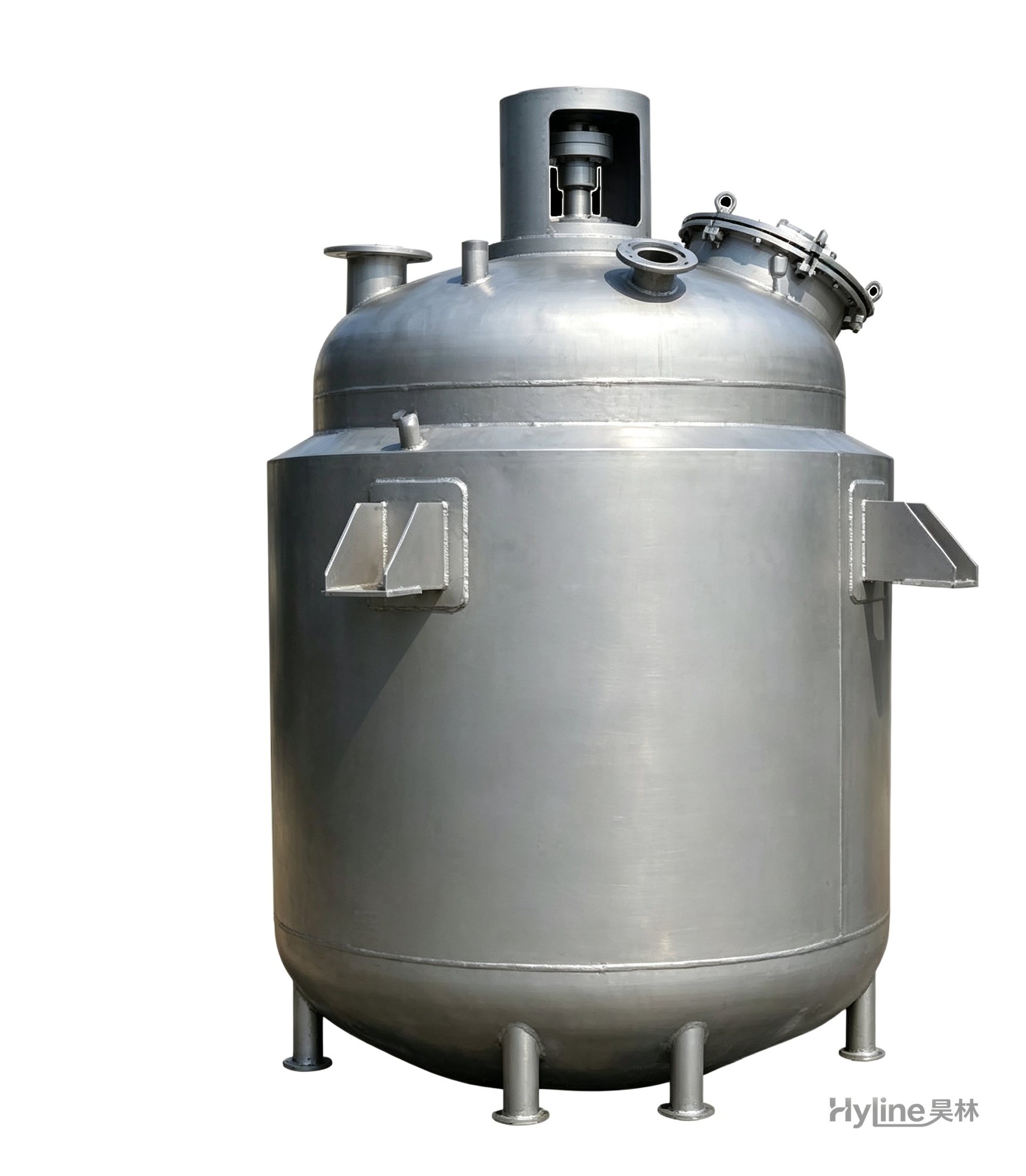
Jacketed Reactor
The typical main reaction vessel in chemical production. Mixing, heating and cooling disperse and mix materials for reaction and polymerization. The jacket circulates thermal oil/steam for heating or cooling water for temperature control.
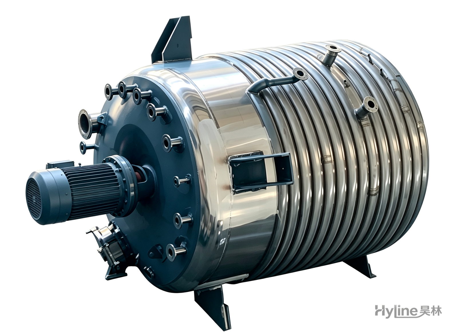
External Half-Coil Reactor
External half-pipe heating & cooling coils provide uniform, efficient heat exchange with zero material dead zones inside. Mirror-polished 304/316L stainless tank is clean and corrosion-resistant. For resin, new-energy slurry and pharmaceutical synthesis.
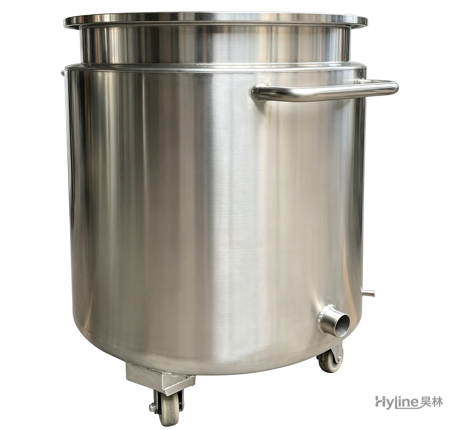
Stainless Steel Mixing Tank (Dispersion Drum)
Supporting vessel for dispersers and mixers in paints, coatings, adhesives, color slurries, inks and electronics. Available in 201/304 stainless with internal/external polishing and sloped bottom side discharge for complete draining.
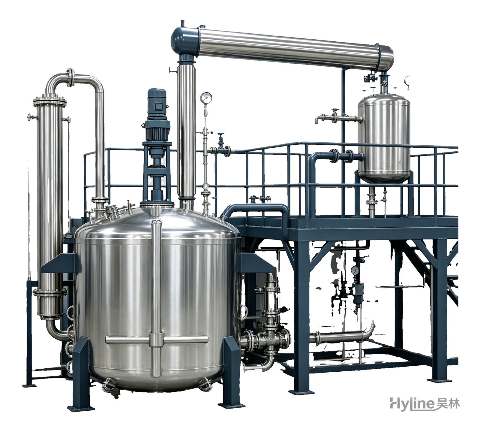
Complete Resin Production Equipment
Resin production packages built around the reactor, with vertical fractionating column, horizontal condenser and water separator for full synthesis, dehydration and reflux processes. Sizes from 300L to 30000L.