
How to Choose Reactor Discharge Methods? Gravity, Pumping and Pressure Discharge by Material Properties
10/11/2026
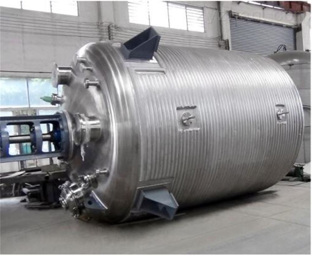
How to Choose Reactor Discharge Methods? Gravity, Pumping and Pressure Discharge by Material Properties
The discharge step of a reactor, though it looks like the last action, actually decides whether a batch can be fully collected and how cleanly. If the discharge method is wrong, viscous materials do not drain completely, pipes block, pumps run dry, or clean materials get contaminated — all common on-site problems. Conclusion first: the discharge method is decided by material viscosity and process requirements — use gravity discharge for low-viscosity materials with head difference, pump discharge for medium viscosity or when transfer distance is needed, and in-tank pressure discharge for high viscosity, rapid emptying or closed discharge, with a bottom discharge valve and pipe slope to minimize residue. This article explains the applicable boundaries and configuration points of the three methods.
### Why is the discharge method worth separate design?
Discharge is not just "opening the valve and letting the material out". For a reactor, the discharge method affects three things: first, yield — how much residue remains directly counts into cost; second, cleanliness — open discharge brings in air and impurities, while closed discharge preserves material quality; third, safety — when volatile or toxic materials are discharged open, on-site odor and occupational exposure are problems. So the discharge method should be decided at the design stage together with agitation and heating; changing the discharge structure after the equipment arrives usually means modifying the tank bottom and piping, which is costly.
### What duty suits gravity discharge?
Gravity discharge relies on head difference and material self-weight; the structure is the simplest and lowest cost. It is generally suitable for low-viscosity, free-flowing liquids where the reactor outlet is higher than the downstream receiving equipment — for example, the reactor on the second floor and the receiving tank on the first floor; opening the bottom discharge valve lets the material flow down by itself. The advantages of gravity discharge are reliability, easy maintenance and no dependence on power equipment; solvents, aqueous liquids and general chemical intermediates are fully covered. One reminder: the gravity discharge rate slows as the level drops, and flow is very slow near emptying, with fair residue control; so gravity discharge is generally fitted with a bottom discharge valve plus a sight glass, operators watch the discharge state, judge when flow nearly stops, and use a little solvent or compressed air sweep to assist emptying when necessary.
### How is pump discharge configured?
Pump discharge is the most common method for medium-viscosity materials, suitable for cases needing transfer distance, controlled discharge rate, or unfixed receiving positions. Pump type is selected by viscosity and cleanliness: centrifugal pumps for low-viscosity liquids, screw or lobe pumps for medium-viscosity resins and emulsions, diaphragm pumps for materials with solids or easy crystallization, and hygienic centrifugal or lobe pumps for food and pharma clean materials. The greatest value of pump discharge is control and transfer: with a VFD the discharge rate is adjustable, and with piping design the material can be delivered to distant or elevated receiving tanks. A practical experience: for high-viscosity pump discharge, keep the pump inlet pipe short, straight and wide, avoiding elbow resistance that causes dry running; after discharge, flush the pipe with solvent or compressed air promptly to prevent residual material from solidifying and blocking.
### How is in-tank pressure discharge implemented? What materials does it suit?
In-tank pressure discharge (pressure discharge) is done in a closed reactor: compressed air or inert gas is introduced into the tank, and the internal pressure pushes the material out through the bottom outlet. It is generally suitable for high-viscosity materials, cases needing rapid emptying, and flammable, explosive or toxic materials requiring closed discharge. The configuration is typically: a top gas inlet valve connected to compressed air or nitrogen piping, a pressure gauge and overpressure protection inside the tank, and a bottom discharge valve rated for the pressure; discharge starts by opening the gas inlet valve to build pressure (generally 0.05–0.2 MPa), then opening the bottom valve, and the material flows out quickly under pressure. The benefits of pressure discharge are speed, thorough emptying and full closure; the prerequisite is that the reactor and piping are designed for pressure — an atmospheric tank cannot simply be pressurized, and safety valves and pressure interlocks are standard.
| Discharge method | Applicable material | Discharge completeness | Closure | Equipment cost |
|---|---|---|---|---|
| Gravity discharge | Low-viscosity liquids | Fair | Open/semi-open | Low |
| Pump discharge | Medium-low viscosity, needs transfer | Good | Good | Medium |
| In-tank pressure discharge | High viscosity, needs rapid emptying | Good | Good | Medium-high |
### What else to consider for high-viscosity discharge?
For high-viscosity materials (resins, paint bases, adhesives, pastes), gravity alone basically cannot empty them, and pumping alone easily runs dry; the most common on-site combination is "pressure discharge + bottom discharge valve + jacketed heating": fit the tank bottom and discharge piping with a jacket or insulation, heat first to lower viscosity, then use pressure or pumping to deliver the material. For very sticky materials that need the tank scraped clean, a hydraulic discharge machine can push the whole drum of material out, or a tiltable shell lets material drain by self-weight plus scraper blades. One reminder: the discharge pipe diameter for high-viscosity materials must be calculated by viscosity, not taken from low-viscosity sizing, otherwise resistance is high, flow slow and batch time extended; pipe heating and insulation must cover valves and elbows to avoid local cold spots that block material.
### How to ensure safety when discharging flammable and explosive materials?
For flammable and explosive materials, the core of discharge is closure and static grounding. Common practice: discharge fully closed, use nitrogen or inert gas for pressure discharge, connect the discharge pipe and receiving container closed to reduce volatile gas escape; ground the tank and piping reliably, control the discharge flow rate within a range to avoid static accumulation from high flow; fit the receiving tank with a breather valve or exhaust treatment to prevent volatile gas accumulating in the receiving space. A special reminder: when discharging flammable materials, operators should not use open receiving buckets directly — connect the discharge outlet to the receiving container with a closed short pipe; if open discharge is unavoidable, assess the on-site hazardous area classification and static risk, and operate with proper grounding and ventilation.
### How is clean-material discharge done?
For food, pharma and fine chemical clean materials, the discharge design must meet hygiene and aseptic requirements. Common practice: hygienic quick-install valves at the bottom outlet, hygienic stainless steel pipe with quick couplings for the discharge line, polished dead-corner-free interior; keep the discharge process closed to prevent microbes and foreign matter entering; clean and sterilize the discharge line between batches with CIP or SIP, and place a drip tray under the outlet to avoid residual drops contaminating the area. For materials requiring sterile transfer, a closed transfer system with aseptic couplings can connect the reactor and downstream vessels into one closed system. A practical experience: keep clean discharge design as simple as possible — fewer fittings mean fewer dead corners; quick couplings are easier to disassemble and clean than welded flanges, but the coupling gaskets must be hygienic grade and replaced periodically.
### How to improve residue control and yield?
Yield loss in the discharge step mostly comes from residue. Four general practices improve yield: first, make the tank bottom conical or sloped so material concentrates toward the outlet; second, keep the discharge pipe short and straight with a drain valve at the low point so residual liquid can drain; third, after discharging high-viscosity material, flush the pipe with solvent or blow with compressed air to recover wall residue; fourth, check the tank bottom and pipe dead corners after discharge, and adjust process or structure when residue is obvious. One reminder: yield is not determined by the discharge method alone, but by the combination of tank bottom, piping, valves and operating habits; recording batch discharge quantity and residue on site and improving continuously is more practical than replacing equipment at once.
### How does the discharge system link to downstream processes?
Reactor discharge is not the end; it must link to downstream processes. Generally consider three connection points: first, receiving mode — whether the material goes directly into a storage tank, filter, packaging machine or a transfer tank, and the inlet height and pipe routing of the receiving equipment must match the outlet; second, metering — for materials needing measurement, fit a flow meter or scale on the discharge line, linked to batch records; third, cleaning linkage — after discharge, the reactor and piping must connect to the cleaning system, and clean thoroughly between batches when changing products. In a complete line, discharge piping should also unify elevation and diameter with upstream and downstream equipment, reducing temporary hose connections on site — a basic condition for stable line operation.
### Summary
The discharge selection order is: decide material viscosity and cleanliness first, choose the main method of gravity, pumping or pressure discharge, then fit the bottom discharge valve, pipe slope and safety accessories, and finally link to downstream processes. Low viscosity by gravity, medium viscosity by pump, high viscosity by pressure; flammable materials closed with static protection, clean materials closed and cleanable; residue control relies on tank bottom structure and piping design. When purchasing a reactor, put material viscosity, discharge rate, clean grade and explosion-proof requirements into the technical agreement so the manufacturer configures the discharge system by duty, and the equipment can be commissioned on first arrival. Below are real photos of a stainless steel reactor and flange sealing; the bottom discharge structure and connection details can be referenced.

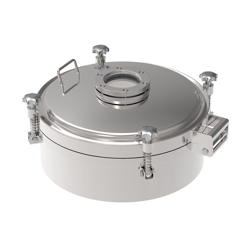
Further reading: - How to configure reactor cover opening: hydraulic lift and quick-open devices - How to choose reactor agitation seals? Mechanical seal vs packing seal by duty
This article is compiled by Shenzhen Hyline Equipment Manufacturing Co., Ltd. (hyline.cn); all information rights belong to the original authors. Main products: stainless steel reactors, mixing tanks, storage tanks, dispersers, concentration tanks and complete chemical process lines; custom (non-standard) manufacturing supported.
Q&A from this article
Frequently asked questions and answers from this article
Gravity discharge relies on head difference and material self-weight; the structure is the…
Related Products
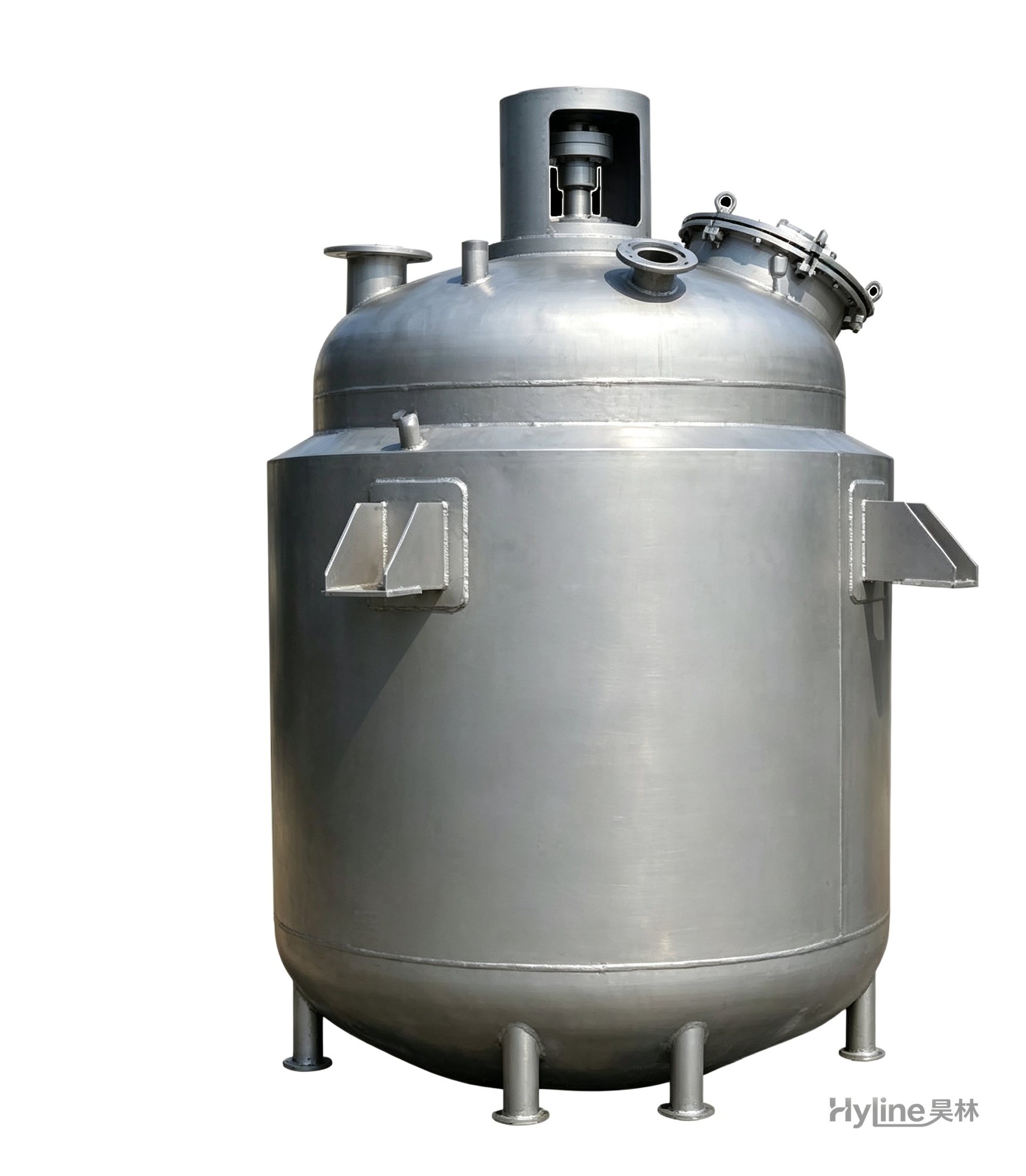
Jacketed Reactor
The typical main reaction vessel in chemical production. Mixing, heating and cooling disperse and mix materials for reaction and polymerization. The jacket circulates thermal oil/steam for heating or cooling water for temperature control.
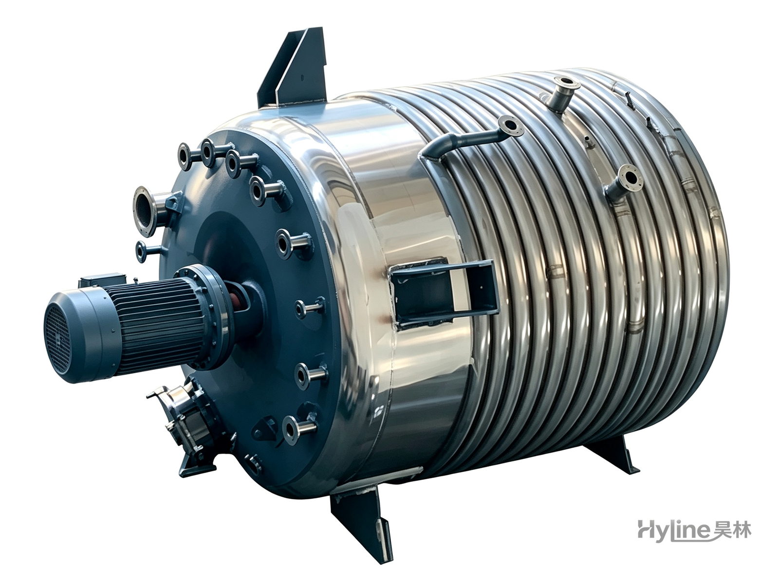
External Half-Coil Reactor
External half-pipe heating & cooling coils provide uniform, efficient heat exchange with zero material dead zones inside. Mirror-polished 304/316L stainless tank is clean and corrosion-resistant. For resin, new-energy slurry and pharmaceutical synthesis.
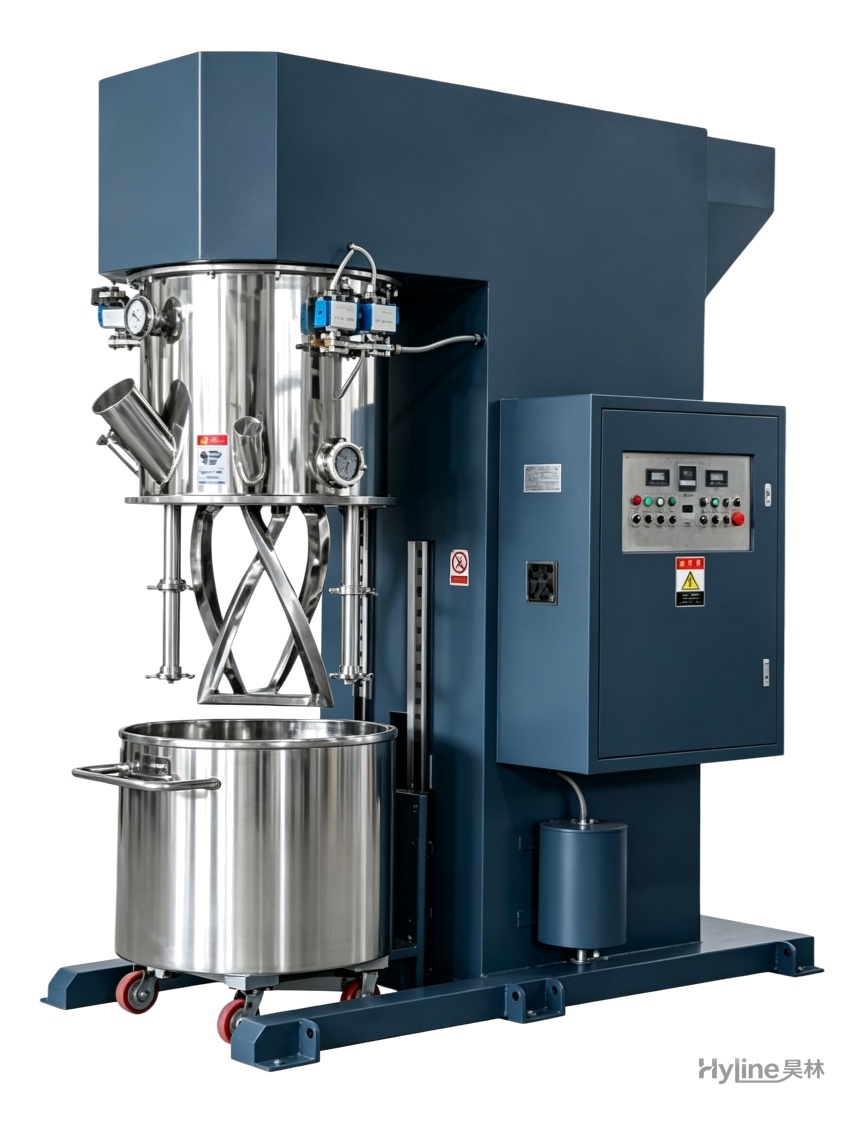
XJB Series Hydraulic Discharge Machine
Works with planetary mixers, power mixers and strong dispersers for pressure filling of viscous flowable materials. Simple structure, easy operation, with a balanced closed-welded steel frame.
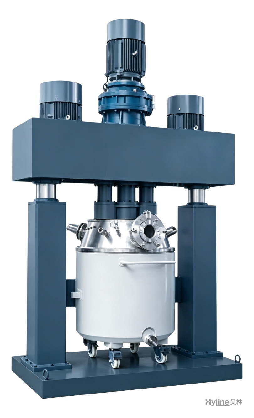
QLF Series Powerful Triple-Shaft Disperser
Two high-speed dispersers plus wall/bottom scraping create complex material flow for rapid dispersion and grinding. Handles high-viscosity pastes of 10,000-2,000,000 cps - widely used for silicone sealants, PU sealants, liquid silicone and electronic adhesives.
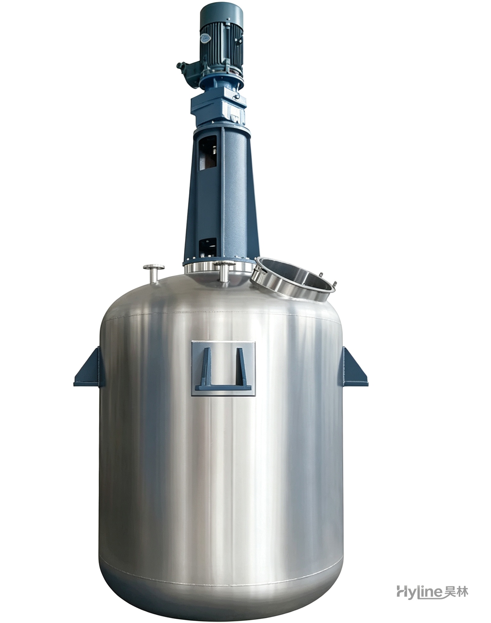
TC Series Mixing Kettle (Tinting)
For color matching in the paint industry and liquid-liquid / liquid-solid mixing in other industries. Uniform tinting, good miscibility, reasonable structure and powerful stirring.
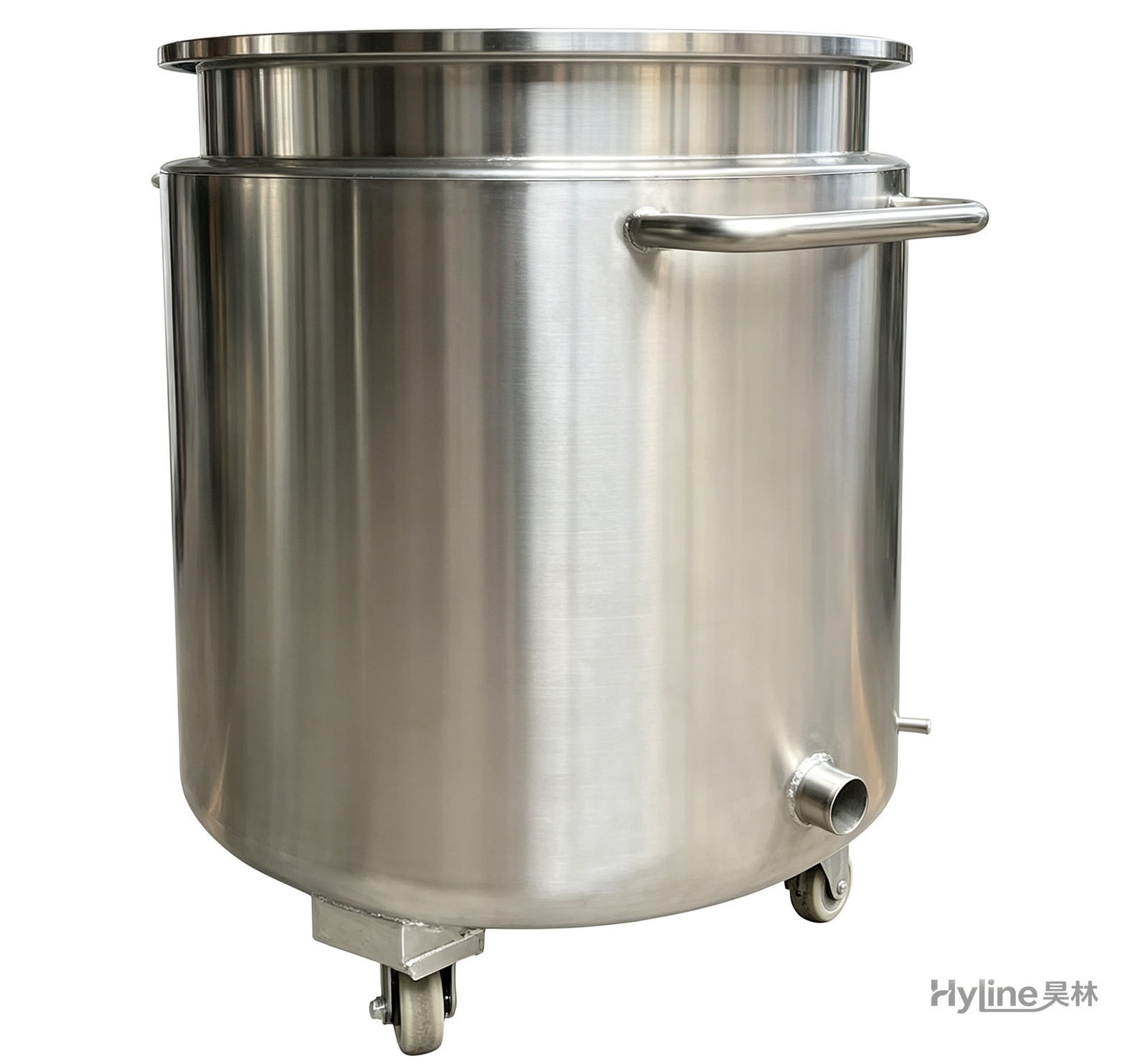
Stainless Steel Mixing Tank (Dispersion Drum)
Supporting vessel for dispersers and mixers in paints, coatings, adhesives, color slurries, inks and electronics. Available in 201/304 stainless with internal/external polishing and sloped bottom side discharge for complete draining.