How to take a representative sample from a reactor: port location, line displacement and sample validity
11/6/2026
What worries a batch reactor operator most? Not slow heating, not uneven agitation, but a sample that does not match the real state inside the vessel. The lab sheet looks fine, yet the discharged batch shows lower conversion or a darker colour — and in the end the test was not wrong, the sample was never representative. Sampling a reactor looks like simply opening a valve and filling a bottle, but where the port sits, whether the line has been flushed, and whether the agitator is still running all decide how far that bottle drifts from the vessel average. This article explains port location, line displacement, sampling timing and representativeness checks so your in-process data means something.
Where does inaccurate sampling usually come from?
In one sentence: most "data that does not add up" is not lab error — the sample itself does not represent the vessel.
The contents are never uniform. Density differences settle heavy components, the layer near the jacket or coil runs cooler and more concentrated, and mixing near the impeller differs from that near the wall. A port in a dead leg or at the end of a stagnant branch returns a local pocket, not the batch average. On top of that, the sampling line usually holds liquid left from the previous batch or the previous draw, so the first seconds out of the valve are stale dead volume. Stack those two errors and even perfect analysis only measures the wrong sample. Check sampling first, then the analytical method — not the instrument straight away.
Where should the sampling port be placed?
In one sentence: a single point rarely represents the whole vessel; put the main port in the active circulation zone at a level that reflects average concentration, and add layered points only when needed.
Common practice places the main port in the lower-middle of the vessel, inside the main agitation loop, away from directly below the feed inlet and from the settling zone near the discharge. That level avoids surface foam and light-phase enrichment while staying in the loop driven by the impeller, so concentration is closest to the batch average. Upper and lower comparison points are added only for processes that track stratification, interfaces or settling. The table below lists what each position is good for:
| Port position | Representativeness | Suitable use | Main risk |
|---|---|---|---|
| Upper liquid | Light phase, foamy | Foam and light-phase checks | Not the batch average |
| Middle main flow | Closest to average | Routine control, endpoint | Keep clear of baffles and thermowells |
| Lower, near discharge | Heavy phase, settled solids | Settling checks, pre-discharge | Picks up sediment, prone to clogging |
| Circulation line | Continuous, representative | Online sampling, continuous reaction | Line must keep flowing |
For segmented heating designs such as a half-coil reactor, port layout must also avoid the welds and supports of each coil section. A nozzle sitting in a high heat-flux area runs hot locally and skews both sample temperature and composition. Fixing port and coil segmentation together at the drawing stage is far easier than cutting a new hole into a pressure shell later.
Why displace the line before sampling?
In one sentence: residual liquid in the sampling line must be flushed out first, otherwise you collect dead-volume stock instead of the current batch.
Between the valve and the bottle there is always a short length of pipe that sits still between draws: it cools, solvent evaporates, and solids-bearing liquid settles or even crystallises. Open the bypass or sampling valve first, drain that stagnant liquid, and only take the official sample once the discharge matches the vessel in temperature, colour and flow. Displacement volume can be estimated at three to five times the line volume, but the more reliable signal is a continuous, bubble-free, non-separated stream at stable temperature — not a stopwatch. For viscous liquids, allow more displacement time.
For crystallising, setting or high-solids liquids, add tracing or a purge: tracing keeps the line from freezing up, while a purge pushes residual liquid back into the vessel after sampling so the next opening does not meet a plug. For clog-prone points, a short, detachable, washable line beats a tidy long loop. A common field situation is a perfectly good sampling valve blocked again and again by one long dead leg — the problem is the layout, not the valve. Routing displacement back into the vessel also cuts product loss and waste treatment.
How to sample a hot or pressurised vessel?
In one sentence: bring vessel conditions into the allowed sampling range first, then open the valve, and prefer closed sampling over an open catch.
Sampling hot liquid can flash and lose light components as soon as it leaves vessel pressure, changing composition on the spot; sampling under pressure is worse, with an instantaneous spray that is both hazardous and distorting. Cool to the specified sampling temperature, vent to atmospheric or slight positive pressure, keep the agitator turning slowly for uniformity, and draw through a cooled closed sampler. A closed bottle also prevents solvent loss and air oxidation, which matters for oxidation-sensitive or hygroscopic systems.
One easily missed detail: do not sample immediately after cooling and venting. The vessel is still re-equilibrating and liquid near the heat-transfer surface differs in temperature from the core. Wait until the temperature curve flattens and the agitator has run a few more minutes. Writing "cool — stabilise — homogenise — displace — sample" into the operating procedure is far more reliable than deciding on the spot each time.
How to set sampling timing without misjudging the endpoint?
In one sentence: sample while agitation runs, at stable temperature, and at a point that is identical batch after batch — only then is endpoint judgement comparable.
Stop the agitator and a solids-bearing system starts stratifying within minutes, so an upper and a lower draw become two different results. Right after a charge or a dosing step, local concentration is not yet uniform and the sample looks "not yet reacted". During heat-up, conversion keeps moving and two draws cannot be compared. Bind control points to the process rhythm, not to the operator's free time. The table below maps typical points to their purpose:
| Sampling point | Purpose | Confirm before drawing |
|---|---|---|
| After charge and homogenising | Verify initial ratio | Agitator running, temperature stable |
| At temperature, early hold | Establish reaction baseline | Temperature curve flat |
| Mid hold | Track conversion trend | Same conditions as previous batch |
| Before expected endpoint | Decide if endpoint is reached | Full displacement, duplicate sample |
| Before discharge | Batch release check | Whole vessel homogenised |
This ties back to the mixing logic of a mixing tank: sample representativeness is essentially a projection of how uniformly the vessel is mixed. No port can return an average from a dead zone the agitator never reaches. So when control data swings, look past the lab — check impeller type, baffles, liquid level and speed for regions that never refresh. Improving mixing is often more fundamental than moving the port.
Can you verify representativeness yourself?
In one sentence: yes — duplicate samples and upper/lower comparison quickly tell you whether sampling is trustworthy.
The simplest check is two consecutive samples from the same point sent separately. If their spread clearly exceeds the lab's own repeatability, the sampling operation or line displacement is at fault. Go further by comparing an upper and a lower draw; a stable difference means the vessel is not homogenised, or the port sits in a stratified zone. Neither check needs extra equipment, yet both separate sampling, mixing and analytical problems the moment control data looks wrong, avoiding a whole batch of rework.
Keep retain samples too. Seal one bottle per batch labelled with batch, time, temperature, pressure and port, and retest it when the finished product deviates — it quickly locates where the drift began. Many unexplained batch swings are finally untangled by one retain bottle. Put these records on a fixed form alongside the sampling sequence, and shift handovers stop depending on one experienced operator's memory.
How to specify ports and valves that do not clog?
In one sentence: short lines, few dead legs and washable joints beat any expensive valve; add tracing or purge for crystallising liquids.
Three valve types are common: ball valves switch fast but trap liquid in the cavity, piston sampling valves have small dead volume and suit solids-bearing liquid, and diaphragm valves seal well for clean service. Judge first whether the liquid scales, crystallises or carries solids, then how it will be cleaned, and only last the price. The table below maps liquid characteristics to valve choice:
| Valve type | Dead volume | Suitable liquid | Maintenance focus |
|---|---|---|---|
| Ball valve | Larger | Low-viscosity, non-crystallising clear liquid | Periodic cavity cleaning |
| Piston sampling valve | Small | Solids-bearing, settling liquid | Purge after displacement |
| Diaphragm valve | Small | Clean, oxidation-sensitive systems | Check diaphragm ageing |
Keep the connection short: seat it on the vessel wall rather than running a long pipe. Where it must reach an operating face, give the line a drainable slope and a low-point drain. Keep the inner end flush with the vessel wall — a protruding stub is exactly where build-up starts. For frequent sampling or multi-product vessels, specify a closed sampler with displacement return and a purge port, so "residue returns to the vessel, line holds nothing" is built into the equipment rather than patched by procedure.
How we build sampling into the equipment
As Hyline Shengda Equipment Manufacturing Co., Ltd. behind hyline.cn, we treat sampling as an interface to be designed with the vessel, not a hole drilled after delivery: port elevation and orientation set by medium, kept clear of coil welds, baffle supports and settling zones; short lines, piston valves and purge ports for solids-bearing or crystallising liquids; cooled closed-sampler connections and displacement return for hot or pressurised service, cutting product loss and spillage.
We also advise telling us medium composition, working temperature and pressure, batch rhythm and which control measurements are needed before ordering, so we can set the number of ports, valve type, tracing and whether online sampling is needed. Sampling looks minor, yet it decides whether control data is usable. If you are fighting drifting sample data, a blocked port or pressurised sampling, share your conditions and we will help you get that one bottle right.
Further reading: - How to arrange temperature and pressure ports on a reactor: thermowells, pressure connections and installation - Factory acceptance of a stainless reactor: no-load run, loaded test and leak check
This article is compiled by Hyline Shengda Equipment Manufacturing Co., Ltd.
Q&A from this article
Frequently asked questions and answers from this article
In one sentence: residual liquid in the sampling line must be flushed out first, otherwise…
Related Products
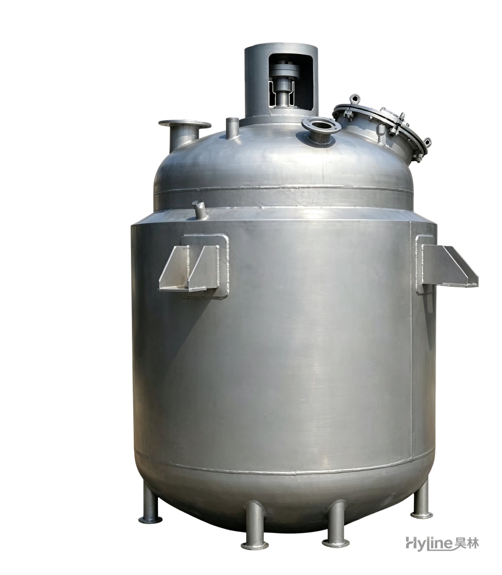
Jacketed Reactor
The typical main reaction vessel in chemical production. Mixing, heating and cooling disperse and mix materials for reaction and polymerization. The jacket circulates thermal oil/steam for heating or cooling water for temperature control.
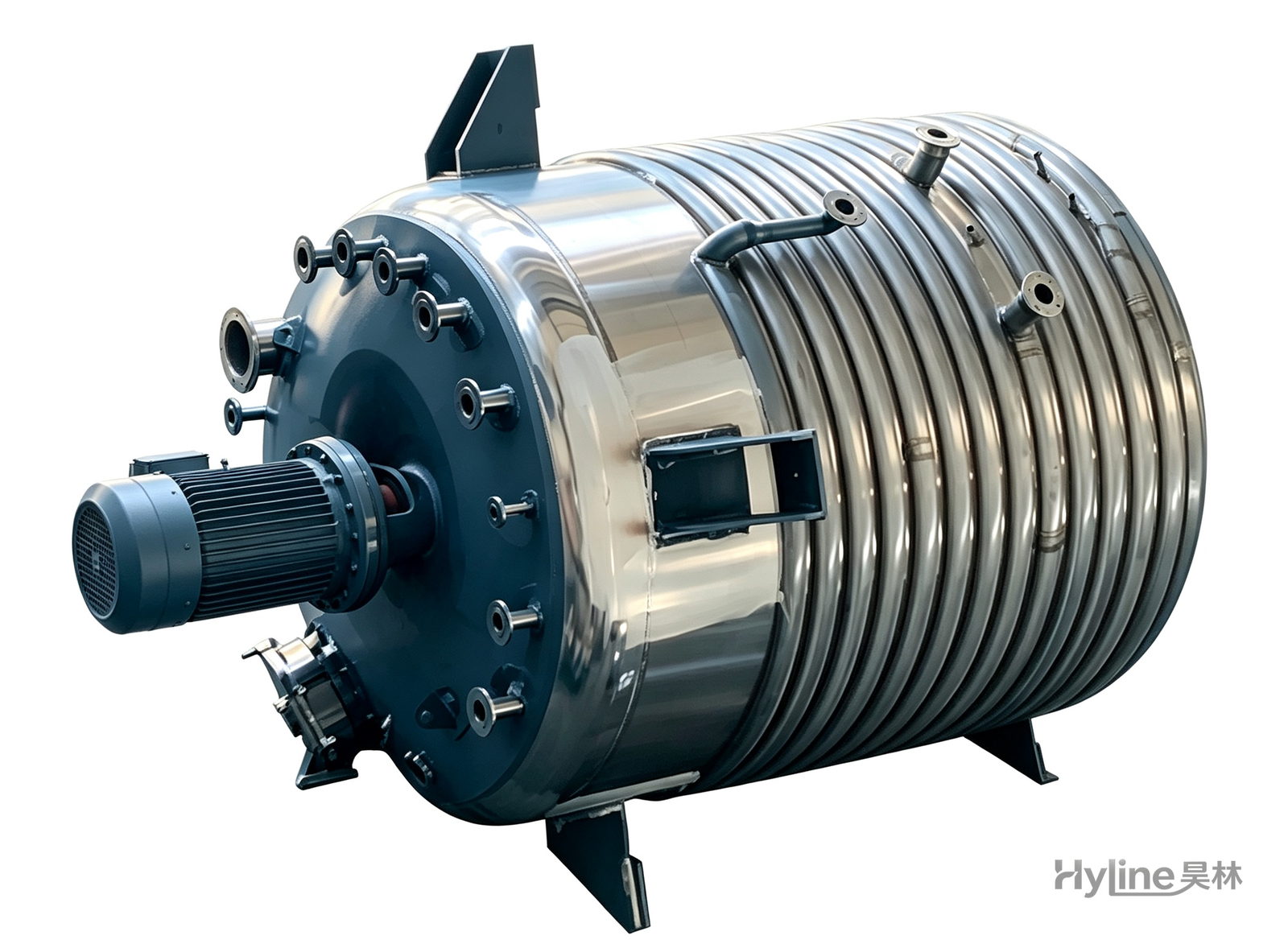
External Half-Coil Reactor
External half-pipe heating & cooling coils provide uniform, efficient heat exchange with zero material dead zones inside. Mirror-polished 304/316L stainless tank is clean and corrosion-resistant. For resin, new-energy slurry and pharmaceutical synthesis.
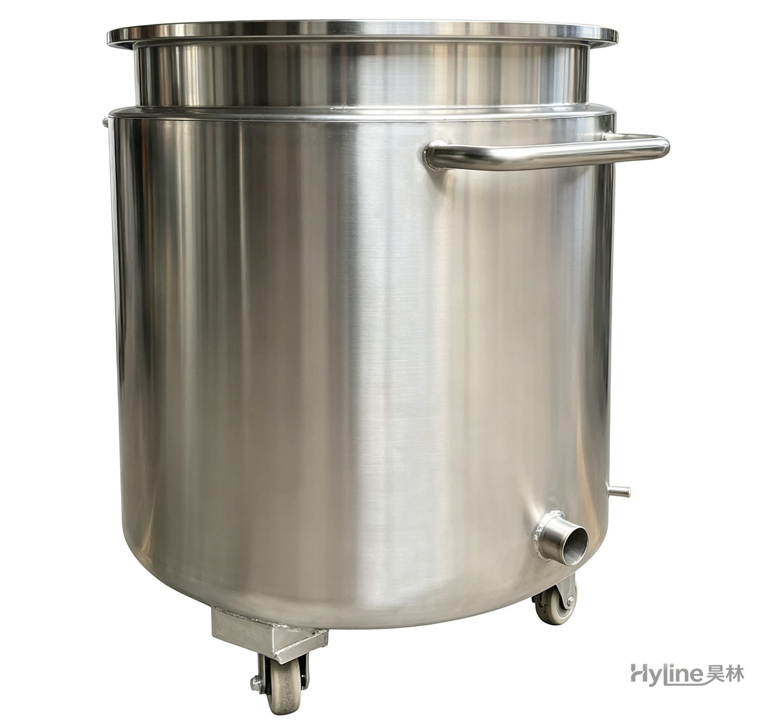
Stainless Steel Mixing Tank (Dispersion Drum)
Supporting vessel for dispersers and mixers in paints, coatings, adhesives, color slurries, inks and electronics. Available in 201/304 stainless with internal/external polishing and sloped bottom side discharge for complete draining.
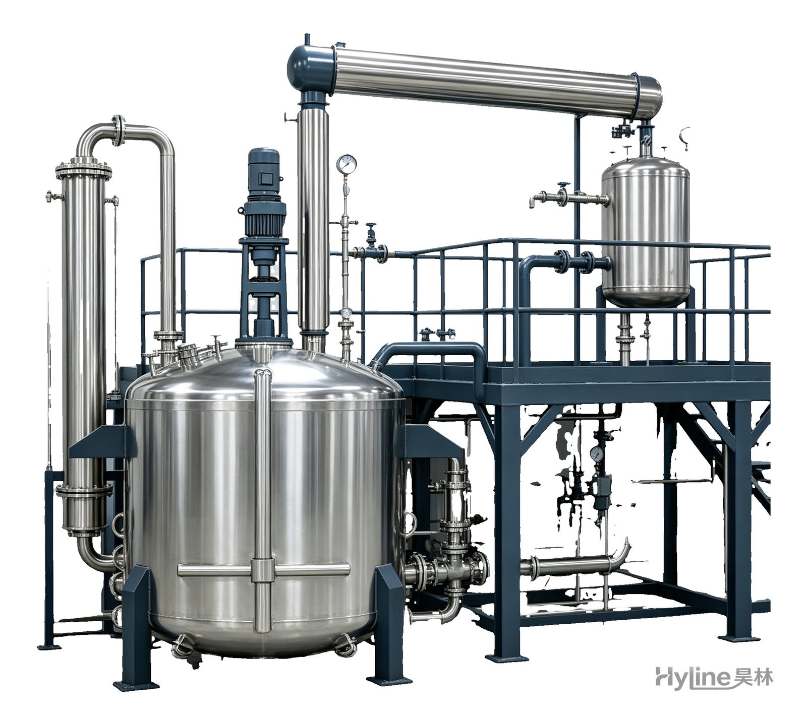
Complete Resin Production Equipment
Resin production packages built around the reactor, with vertical fractionating column, horizontal condenser and water separator for full synthesis, dehydration and reflux processes. Sizes from 300L to 30000L.