
How to Arrange the Temperature and Pressure Ports of a Reactor? Thermowell, Pressure Connection and Installation Specifications
10/15/2026
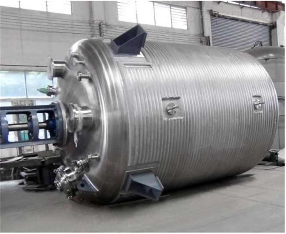
The temperature and pressure data of a reactor are the eyes of batch control. If the temperature port is arranged poorly, the displayed temperature differs from the true liquid temperature by 5-10℃ and process adjustment follows the error; if the pressure port position is wrong, readings fluctuate or plug up, and safety interlocks become useless. In many reactor instrument problems, the root cause is not the instrument itself but the nozzle arrangement. This article explains the arrangement points from four aspects: thermowell insertion depth, pressure tap position, nozzle size and sanitary installation; final dimensions are checked against design codes and process requirements.
Why Should the Temperature and Pressure Ports Be Studied Separately?
One-line conclusion: nozzle arrangement decides whether instrument data represents the real condition; with wrong arrangement even the best instrument is useless.
The temperature distribution inside a reactor is not uniform: the difference between wall and center, liquid and gas phase, bottom and top is significant. Where the temperature port is installed and how deep it probes decide whether the instrument reads "representative liquid temperature" or "local temperature". The same applies to pressure: a tap in the stirring vortex zone fluctuates with the liquid level; in the gas phase zone it stably reflects the internal pressure. Temperature and pressure measurement are the data source of safety interlocks and process control, and nozzle arrangement is decided at the design stage - it is troublesome to change after the equipment arrives. This article explains the arrangement rules along the temperature and pressure lines for process and equipment personnel to check the drawings.
How to Arrange the Temperature Port? Position and Insertion Depth
One-line conclusion: install the temperature port on the lower middle of the tank side wall, with the element insertion depth generally one-third of the tank inner diameter, avoiding the impeller sweep zone.
The port position affects the representativeness of the reading. Common arrangement: lower middle of the side wall, below or beside the impeller, where mixing is sufficient and the temperature represents the bulk liquid; insertion depth is generally one-third of the tank inner diameter - too shallow only measures near-wall temperature, too deep enters the impeller sweep zone with a collision risk. Top-inserted temperature ports are used near the stirring shaft or at specific levels and need clearance from the stirring assembly. A mixing tank is arranged the same way as a reactor, with the probe depth about one-third of the tank diameter; multi-point temperature measurement (multiple points in the kettle) is common for differential-sensitive processes, using 2-3 elements with average or highest value in control. In the technical agreement, write the number, position (side/top) and insertion depth of the temperature ports, and check against impeller dimensions to avoid installation interference.
How to Choose between Thermowell and Direct-Contact Measurement?
One-line conclusion: regular reactors use a thermowell to protect the element - wear-resistant, pressure-resistant and removable under pressure; direct-contact type is only for processes with extremely high response requirements.
The thermowell isolates the temperature element from the liquid, protecting it from corrosion, wear and high pressure, and allowing replacement without stopping production. The cost is slower response: the wall thickness and gap delay heat transfer, generally 30 seconds to several minutes slower than direct contact. Selection points: corrosive liquids use metal wells (316L, Hastelloy or PTFE-lined), high-pressure conditions calculate wall thickness by design pressure, and fast-response requirements use thinner well tips or thermally conductive paste filling the gap. The thermowell of an external half-coil reactor shares the same wall as the jacket side, so keep clearance from the coil welds during arrangement to avoid welding stress affecting the well seal. Direct contact responds fast but the element is exposed and replacement stops production; it is used for high-sanitation or extremely fast-response processes. Most chemical reactors choose the thermowell type and write response time into the instrument specification.
How to Arrange the Pressure Connection? Tap Position and Anti-Plugging
One-line conclusion: install the pressure tap in the top gas-phase zone, avoiding the stirring vortex, foam and level fluctuation zones, with anti-plugging purging where needed.
Stable internal pressure readings depend heavily on the tap position. Common practice: install the tap on the top or upper side wall gas-phase zone, where the pressure represents the internal gas pressure; avoid the vortex, foam layer and level fluctuation range of stirring, otherwise readings fluctuate. Viscous materials or slurries with solid particles easily plug the pressure line; add anti-plugging measures: an isolation vessel or diaphragm before the transmitter, or a nitrogen micro-purge to keep the line clear. For vacuum conditions, pay attention to the air tightness of the line, since leakage under negative pressure affects the vacuum reading. In the agreement, write the tap position and anti-plugging form (diaphragm/purge/isolation vessel) to avoid frequent plugging after commissioning.
How to Decide Nozzle Size and Flange Standard?
One-line conclusion: size the temperature and pressure nozzles by instrument connection and process opening, keep the flange standard consistent with the tank, generally DN25-DN50, and check the weld form and seal.
The nozzle size is decided by the instrument connection: thermowells use M27x2 or 1/2NPT thread connections, and flanged connections are commonly DN25-DN40; pressure connections use DN25-DN50 flanges or corresponding threads. The flange standard matches the tank (GB, HG, ANSI per project), pressure rating follows the internal design pressure, and vacuum conditions choose vacuum-grade seals. The weld form affects cleanliness: sanitary reactors use butt weld or clamp connections to avoid dead corners; ordinary chemical use uses flat-weld flanges. The nozzle extension length matches the insulation thickness - too long affects operation, too short buries the connection in the insulation after lagging. At the drawing stage, check the nozzle orientation drawing (nozzle schedule) item by item, confirming dimensions, flange standard and extension length together.
Sanitary Installation Requirements for Clean Conditions
One-line conclusion: for pharmaceutical and food clean reactors, reduce dead corners at the temperature and pressure ports, use sanitary clamp connections and quick-open structures, and ensure clean-in-place after installation.
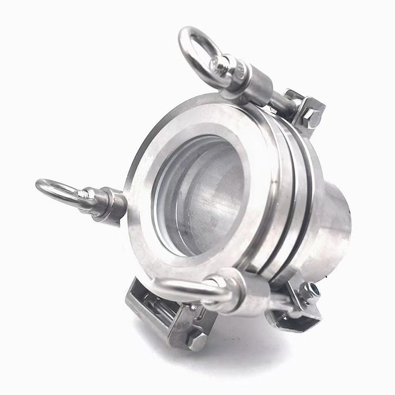
The design principle of clean-condition nozzles is "no dead corners, cleanable". Thermowells use sanitary structures with clamp or thread connections to the wall and surface roughness consistent with the inner wall; pressure tapping uses diaphragm seals or sanitary transmitters to avoid residual material in the line. Installation direction matters too: temperature ports avoid upward open mouths that accumulate material, and pressure ports are angled or inverted to reduce residual liquid. For reactors requiring clean-in-place (CIP), the port position must be covered by the cleaning spray ball and the well must not block the spray path. Instrument selection for clean conditions also considers material (316L, electropolished) and certification requirements, with the sanitary grade written into the instrument specification and nozzle drawings.
How to Avoid Interference between Ports and Stirring?
One-line conclusion: check the nozzle arrangement against the stirring assembly (impeller, baffles, thermowell) on drawings for interference, keeping the impeller sweep zone and baffle positions clear of the temperature probe depth.
The space inside a reactor is limited; clearance among temperature elements, pressure lines, baffles, impellers and coils is a mandatory drawing-stage check. Check the probe depth against the impeller sweep radius: if the insertion depth enters the sweep zone, the well can be bent or broken under high-speed operation; pressure lines interfering with baffles in the level fluctuation zone affect readings and cleaning. Common practice: fix the stirring assembly first (impeller type, diameter, baffle positions), then arrange instrument nozzles, and finally do a 3D interference check. When multiple nozzles are on the same side, allow operating space so flange bolts can be removed normally. Write these check items into the equipment design review checklist, since rework after delivery is expensive.
What Are the Common Arrangement Mistakes?
One-line conclusion: common mistakes include shallow temperature ports with inaccurate readings, pressure taps in the vortex zone with fluctuations, pressure lines without anti-plugging, and dead corners in clean tanks; check item by item at the drawing stage.
Several high-frequency problems: first, a temperature port reaching only near the wall shows near-wall temperature lower than the bulk liquid; second, a pressure port in the stirring vortex or level fluctuation range gives fluctuating readings and false interlock actions; third, viscous liquid pressure lines without diaphragm or purge plug once a week after commissioning; fourth, clean tanks with threaded dead-corner connections that cannot be cleaned; fifth, the nozzle orientation drawing is not checked and the flange orientation hits a platform or adjacent piping on arrival. The common point is that "instrument data must represent the real condition" was not taken as a design input at the drawing stage. Check item by item according to sections two to seven of this article and most can be avoided.
Installation and Acceptance Points
One-line conclusion: check insertion depth, seal and orientation during installation; compare temperature and pressure data and run leak tests during acceptance, recording item by item.
Installation stage points: insert the thermowell to the drawing depth and fix it, clean the sealing faces, tighten flange bolts evenly in a diagonal sequence; before connecting the pressure port, confirm the diaphragm or purge line is open. Acceptance stage: after filling with water or material, compare the instrument display with the process expectation - for temperature error, check insertion depth and well heat conduction first; for pressure fluctuation, check tap position and purge; run leak tests to confirm nozzle seals, and vacuum-pressure holding for vacuum kettles. Archive the commissioning records and nozzle drawings as the basis for later maintenance. The acceptance standard for reactor temperature and pressure ports is "reliable data, maintainable"; execute installation and acceptance accordingly and instrument problems after commissioning drop significantly.
Further Reading
- How to Choose Reactor Stirring and Sealing? Impeller Types, Mechanical Seals and Operation Maintenance Points
- How to Arrange Mixing Tank Nozzles? Feed, Discharge and Instrument Ports by Process
This article is provided by Haolin Shengda Equipment Manufacturing Co., Ltd. (hyline.cn), specializing in stainless steel reactors, mixing tanks, storage tanks, dispersers, concentrators and complete chemical line support, with non-standard customization available.
Q&A from this article
Frequently asked questions and answers from this article
The arrangement of reactor temperature and pressure ports decides instrument reliability: the temperature element insertion depth is generally one-third of the tank diameter and the pressure tap avoids the stirring vortex zone; this article gives port position, size and installation acceptance points.
Related Products
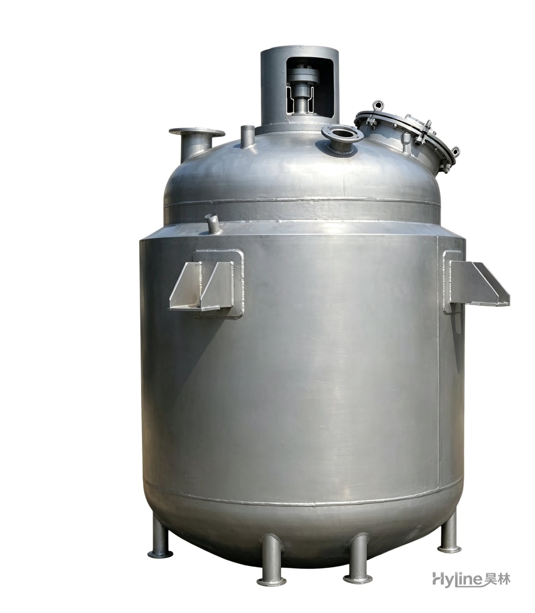
Jacketed Reactor
The typical main reaction vessel in chemical production. Mixing, heating and cooling disperse and mix materials for reaction and polymerization. The jacket circulates thermal oil/steam for heating or cooling water for temperature control.
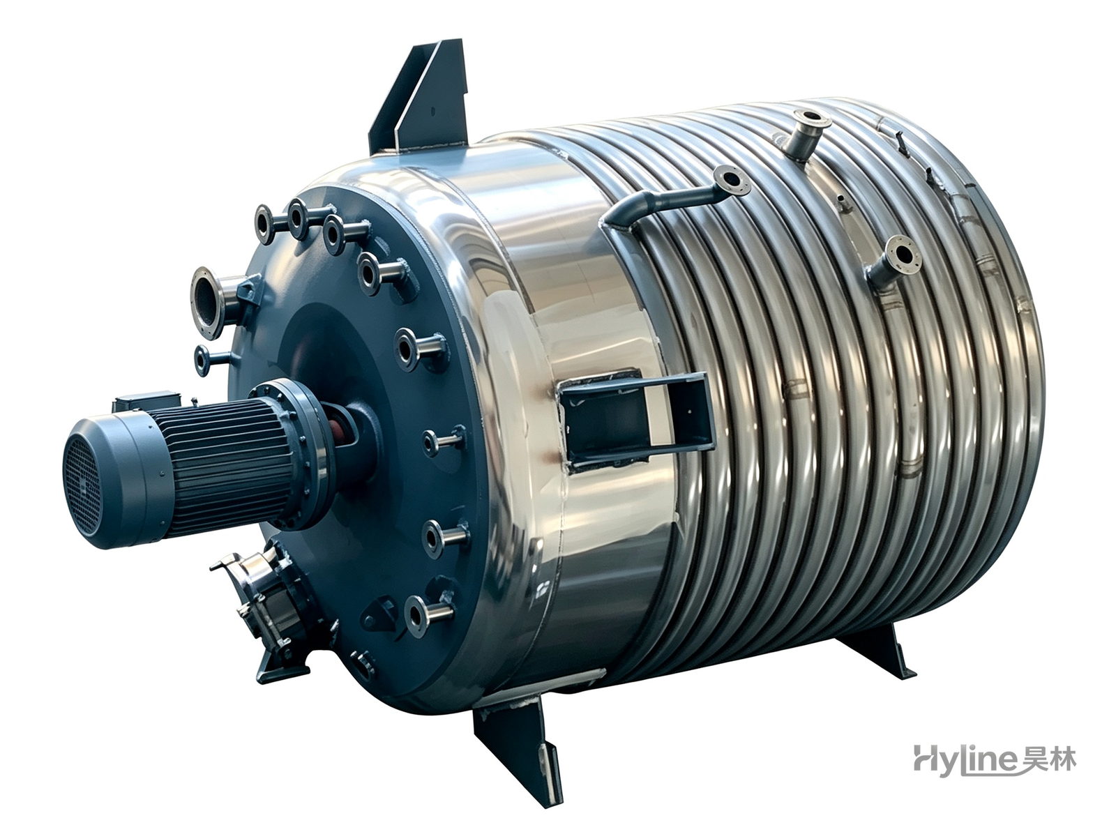
External Half-Coil Reactor
External half-pipe heating & cooling coils provide uniform, efficient heat exchange with zero material dead zones inside. Mirror-polished 304/316L stainless tank is clean and corrosion-resistant. For resin, new-energy slurry and pharmaceutical synthesis.
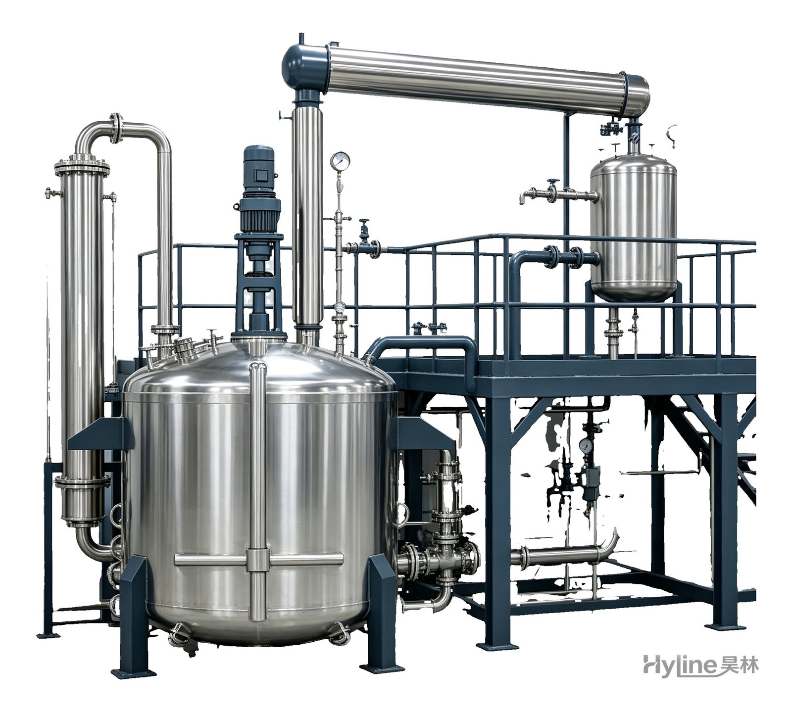
Complete Resin Production Equipment
Resin production packages built around the reactor, with vertical fractionating column, horizontal condenser and water separator for full synthesis, dehydration and reflux processes. Sizes from 300L to 30000L.
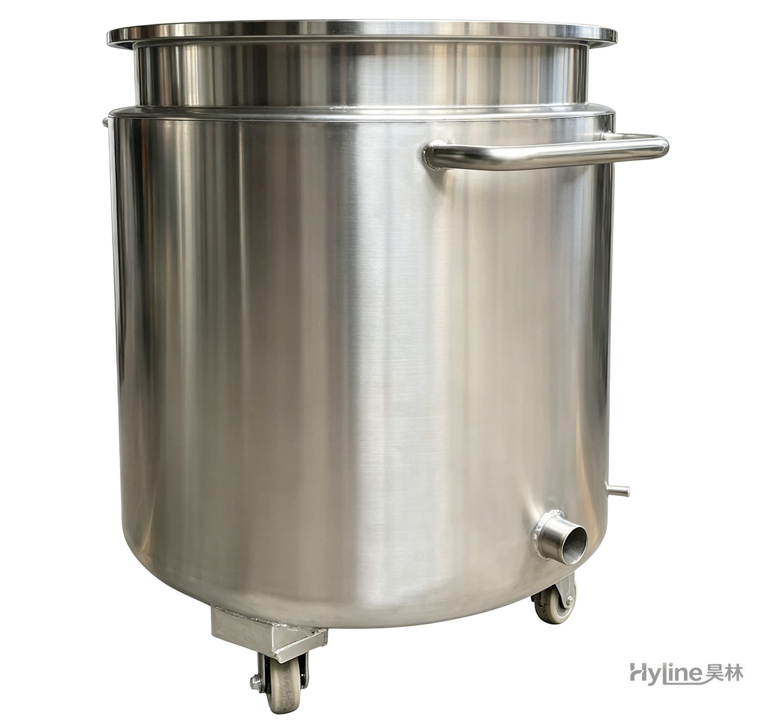
Stainless Steel Mixing Tank (Dispersion Drum)
Supporting vessel for dispersers and mixers in paints, coatings, adhesives, color slurries, inks and electronics. Available in 201/304 stainless with internal/external polishing and sloped bottom side discharge for complete draining.