
How to Configure a Reactor Vacuum System? Vacuum Pump, Buffer Tank and Piping Essentials
10/15/2026
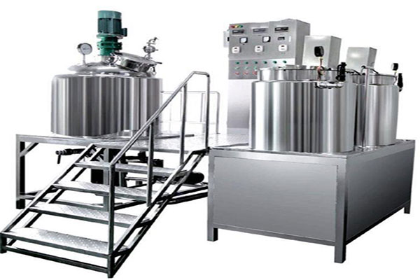
What Does a Reactor Vacuum System Do?
Short answer: the reactor vacuum system handles vacuum feeding, vacuum deaeration, vacuum distillation and material protection, and is a key support for stable reaction processes.
Stainless steel reactors handle mixing, reaction, heating, cooling and material transfer in production, and many of these steps depend on a vacuum environment. Vacuum feeding draws liquid materials from a storage tank into the vessel, avoiding material exposure and heat loss caused by opening the cover for loading. Vacuum deaeration removes bubbles entrained by agitation under negative pressure, improving product appearance and uniformity. Vacuum distillation lowers the boiling point of materials under vacuum, so heat-sensitive materials can complete solvent recovery or concentration at lower temperatures. For processes that must be isolated from air, vacuum or nitrogen blanketing maintains an inert atmosphere inside the vessel. A complete reactor vacuum system generally consists of a vacuum pump, a buffer tank, a condenser, piping, valves and vacuum instruments. The configuration is determined by the process vacuum level and pumping capacity; pump type, buffer tank volume, pipe diameter and material can all be customised to the working conditions.
What Vacuum Level Does a Reactor Need? Set the Grade by Process First
Short answer: vacuum levels fall into three grades by process target; generally check the boiling point and heat sensitivity of the material before setting the target value.
Rough vacuum of about -0.05 to -0.08 MPa is commonly used for vacuum feeding and general deaeration. For example, when a medium-viscosity resin needs deaeration after reaction, drawing the vessel to the rough vacuum range makes bubbles expand and rise rapidly under negative pressure; combined with agitation, deaeration is usually completed in 10 to 30 minutes, with the exact time confirmed by process trials.
Medium vacuum of about -0.08 to -0.095 MPa is used for solvent recovery and vacuum distillation. Taking solvent recovery as an example, a solvent with a relatively high boiling point needs a high temperature for distillation at atmospheric pressure; after drawing to medium vacuum the boiling point drops, and the heating temperature can generally be reduced by 20 to 40 C, saving energy and reducing thermal damage to the material.
High vacuum above -0.095 MPa is used for low-temperature distillation of heat-sensitive materials, such as fragrances and pharmaceutical intermediates, where the distillation temperature can generally be kept below 60 C to avoid decomposition at high temperature.
When selecting equipment, write the process vacuum level into the technical parameter sheet. The ultimate vacuum of the pump should generally be 10 to 20% higher than the target value to leave margin for piping pressure drop and instrument error.
How to Choose a Vacuum Pump? Rotary Vane vs Water Ring
Short answer: small and medium reactors generally use rotary vane pumps; when solvent vapour or dusty gas must be handled, use a water ring pump.
Rotary vane pumps offer a high ultimate vacuum, generally reaching 0.1 to 0.5 kPa, with stable pumping capacity and a compact structure, suitable for clean vacuum duties; their drawback is poor resistance to liquid, so front-end protection such as a gas-liquid separator or buffer tank is needed when pumping gas carrying liquid. Water ring pumps use water as the working medium, resist corrosion and can handle wet gas and gas carrying liquid, suitable for solvent recovery and corrosive gas duties; their ultimate vacuum is lower, generally about 3 to 10 kPa, and pumping capacity fluctuates with water temperature, so circulation water temperature should be watched in winter.
Pumping capacity is generally estimated from reactor volume and air change rate: for batch processes an air change rate of 8 to 15 times per hour can be used; for continuous evacuation, calculate from the total volume of piping and equipment, then apply a safety factor of 1.2 to 1.5 when selecting the pump.
| Item | Rotary Vane Pump | Water Ring Pump |
|---|---|---|
| Ultimate vacuum | 0.1 to 0.5 kPa | about 3 to 10 kPa |
| Pumping capacity | stable, adjustable | fluctuates with liquid ring temperature |
| Liquid resistance | poor, needs front protection | good, can handle wet gas |
| Maintenance | oil change, blade check | water change, impeller check |
| Suitable duties | clean vacuum, high vacuum level | solvent vapour, corrosive gas |
Why Are a Buffer Tank and Condenser Necessary?
Short answer: the buffer tank prevents material from being sucked back into the pump, and the condenser recovers vapour solvent and reduces the load on the pump.
The buffer tank is installed between the pump inlet and the vessel. When vessel pressure fluctuates or condensate accumulates, the buffer tank receives the back-flowing liquid, preventing material from entering the pump and damaging components. Buffer tank volume is generally sized for a buffer capacity corresponding to 1 to 2 minutes of pump capacity; the tank is fitted with a drain valve and a level sight glass for routine inspection and discharge.
The condenser is installed between the vessel and the buffer tank to condense and recover solvent vapour evaporated from the process, reducing solvent loss on one hand and lowering the gas load entering the pump on the other. Condenser area is generally estimated from the evaporation rate and the latent heat of the solvent; the temperature difference between cooling water inlet and outlet is usually kept at 5 to 10 C, and when the outlet temperature is too high, cooling water flow or heat exchange area should be increased. Vacuum pump power is matched to pumping capacity and ultimate vacuum; small and medium reactors generally use a pump motor of 2.2 to 7.5 kW, with the exact value based on the pump performance curve.
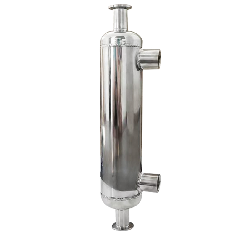
How to Lay Out Piping and Valves? Keep It Short, Straight and with Few Bends
Short answer: vacuum piping should be short and straight with few bends, the pipe diameter no smaller than the pump inlet, and vacuum-grade gaskets at flanges.
The longer the piping and the more bends, the greater the pressure drop and the lower the vacuum actually reaching the vessel. The general principle is to place the pump as close to the vessel as possible, keep pipe diameter no smaller than the pump inlet, and remember that for the same pipe diameter each extra bend increases equivalent piping length by about 1 to 2 metres, which should be included when selecting the pump.
Vacuum ball valves or diaphragm valves are generally used, and connections should preferably be welded or flanged to reduce threaded joints, which are prone to slow leaks. Vacuum-grade nitrile or fluororubber gaskets are used at flanges, and the flatness of sealing faces should be checked during installation. There are three routine check points for holding vacuum: the pump inlet, the buffer tank outlet and the vessel nozzle; vacuum gauge connections should be reserved at all three positions for staged leak testing.
How to Operate Vacuum Feeding and Deaeration?
Short answer: vacuum feeding and deaeration follow the sequence "evacuate first, feed next, break vacuum last", with smooth pressure changes.
For vacuum feeding, close the vent valve first, open the vacuum valve to draw the vessel to the target vacuum level, then open the feed valve to draw material in by pressure difference; after feeding, close the feed valve first and then break vacuum slowly to avoid material splashing. For deaeration, the vacuum level is generally raised in stages: first draw to rough vacuum and hold for several minutes, then gradually raise to the target value. Agitation speed is generally reduced to about half of the process value to prevent high-speed agitation from entraining new air. The specific pressurising rate and holding time are generally confirmed by process trials, as they differ widely between materials.
What Should Be Noted When Several Reactors Share One Vacuum System?
Short answer: use a header with independent branch valves for each reactor so that the reactors do not interfere with each other.
Sharing one vacuum system across several reactors lowers equipment investment, but two points should be noted: first, the header diameter should be calculated from the sum of the pumping capacity of all reactors plus margin; second, each reactor branch should have an independent valve, and the branch valve of an idle reactor should be closed first during operation to prevent vacuum fluctuation from crosstalk. For a shared system, install a main buffer tank at the end of the header, sized at 1.5 to 2 times the buffer capacity of the largest single reactor, to cover the possibility of simultaneous back-flow from several reactors. For vacuum concentration or multi-reactor linked operation, plan the vacuum system together at the whole-line level.
How to Check Seals and Leak Points of the Vacuum System?
Short answer: common leak points are flanges, valve packing and instrument connections; check them by staged pressure testing and leak detection liquid.
Each additional sealing face at a flange joint adds one more leak point. During installation check the flatness of sealing faces, center the gasket and tighten bolts diagonally in stages. Valve packing and the valve stem area are also frequent slow-leak locations; use vacuum-grade packing and tighten it periodically. Instrument connections preferably use welded or ferrule-type joints, with the ferrule nut tightened to the manufacturer's torque. The detection method is generally staged pressure testing first: close the pump and observe the vacuum decay rate of each section; where the vacuum drops fastest, check that section point by point with leak detection liquid. A vacuum gauge together with soapy water applied to flanges and connections can also be used — bubbles indicate a leak.
How to Switch Between Vacuum and Nitrogen Blanketing?
Short answer: for duties that need both air isolation and negative-pressure operation, configure both vacuum and nitrogen interfaces, and vent first before nitrogen filling or break vacuum before evacuation.
Some materials need vacuum deaeration and then nitrogen blanketing immediately after breaking vacuum to keep air out. Configure three lines on the vessel top: a vacuum valve, a nitrogen valve and a vent valve. Operation order: close the vacuum valve, slowly vent to atmospheric pressure, then open the nitrogen valve to fill nitrogen to slight positive pressure; when switching from nitrogen blanketing back to vacuum, close the nitrogen valve, vent, then evacuate. Install check valves between the two lines to prevent nitrogen from entering the vacuum piping. For duties with frequent switching, solenoid valves and pressure interlock can be added; manual or automatic mode is generally configured per process requirements.
How to Troubleshoot When Vacuum Cannot Be Reached?
Short answer: first check the pumping capacity and ultimate vacuum of the pump, then look for piping leaks and condenser liquid accumulation.
Generally measure vacuum stage by stage from the pump inlet, the buffer tank outlet and the vessel nozzle; wherever the vacuum drops fastest, look for the leak there. If pump inlet vacuum is normal but vessel inlet is low, the problem lies in the intermediate piping or valves; if the pump inlet itself cannot reach the ultimate vacuum, check the oil level, blade wear or water ring temperature. Insufficient condenser cooling or liquid accumulation also drags down the vacuum; check cooling water flow and the drain valve, and discharge accumulated liquid promptly.
Procurement Checklist
Write four items into the technical agreement during selection: process vacuum level, pumping capacity, material corrosiveness and whether solvent recovery is required. When configuring a complete production line, check the interface sizes and height differences between the vacuum system, reactors, condenser and storage tanks together to avoid rework on site. Haolin Shengda Equipment Manufacturing Co., Ltd. provides non-standard design and matching of reactor vacuum systems, customised to process parameters.
Further Reading
This article is provided by Haolin Shengda Equipment Manufacturing Co., Ltd. (hyline.cn), specializing in stainless steel reactors, mixing tanks, storage tanks, dispersers, concentrators and complete chemical line support, with non-standard customization available.
Q&A from this article
Frequently asked questions and answers from this article
Short answer: the reactor vacuum system handles vacuum feeding, vacuum deaeration, vacuum …
Related Products
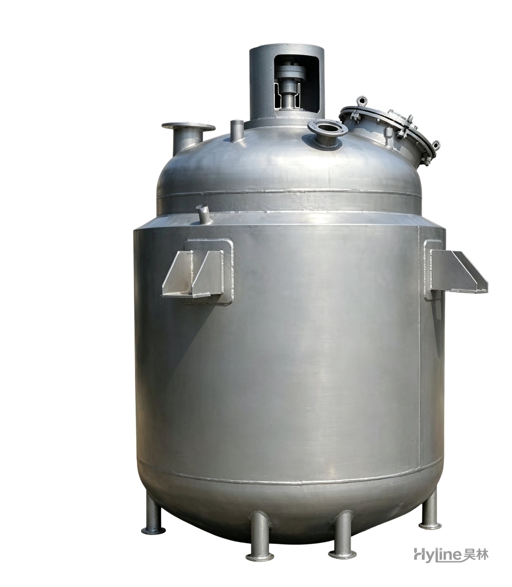
Jacketed Reactor
The typical main reaction vessel in chemical production. Mixing, heating and cooling disperse and mix materials for reaction and polymerization. The jacket circulates thermal oil/steam for heating or cooling water for temperature control.
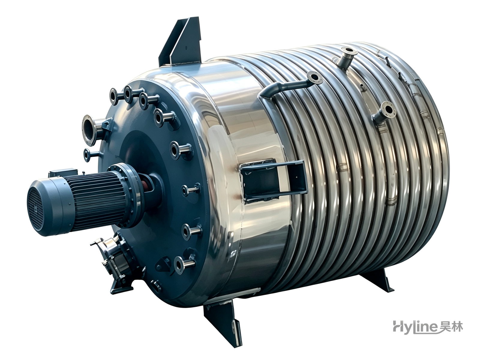
External Half-Coil Reactor
External half-pipe heating & cooling coils provide uniform, efficient heat exchange with zero material dead zones inside. Mirror-polished 304/316L stainless tank is clean and corrosion-resistant. For resin, new-energy slurry and pharmaceutical synthesis.
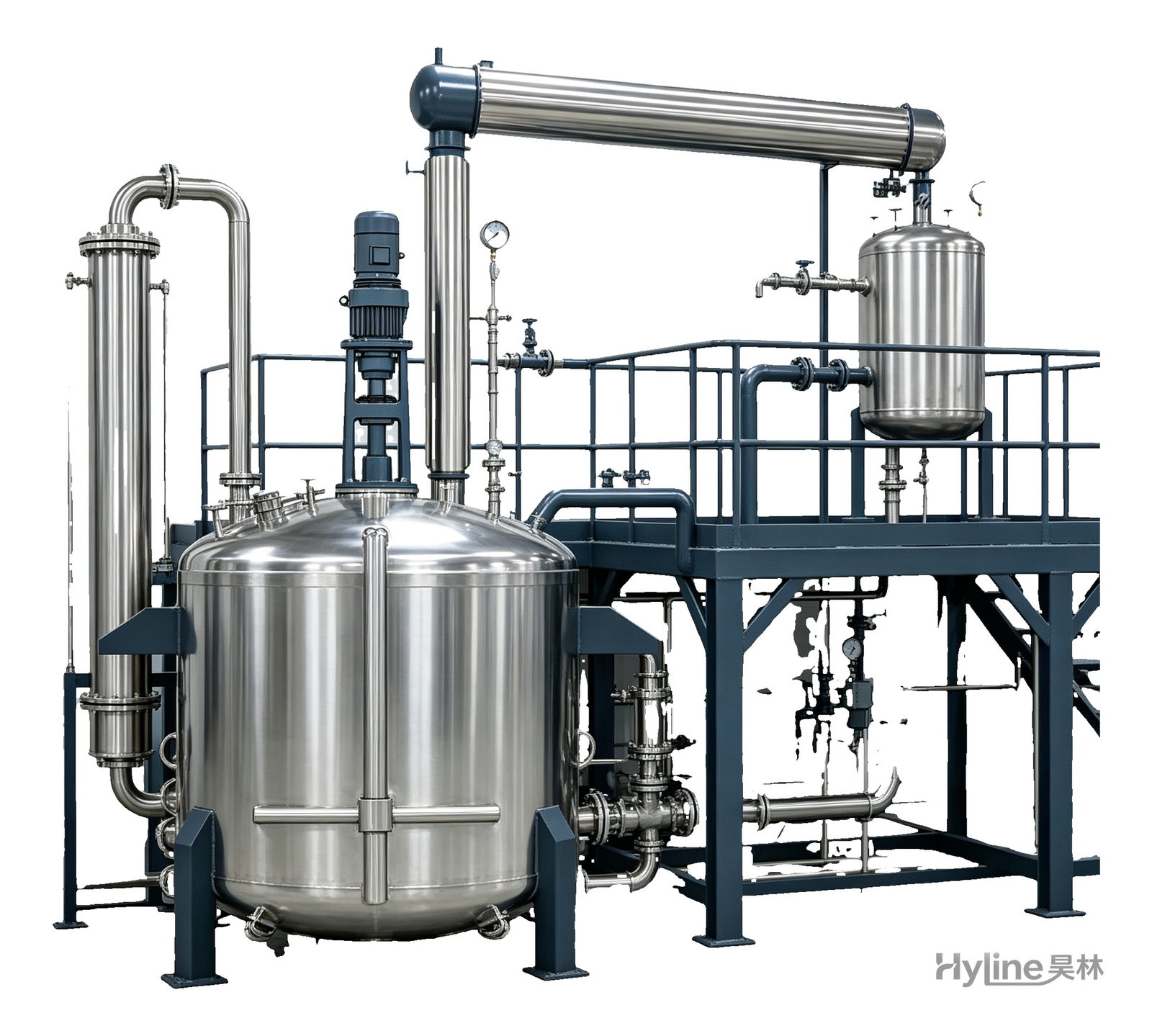
Complete Resin Production Equipment
Resin production packages built around the reactor, with vertical fractionating column, horizontal condenser and water separator for full synthesis, dehydration and reflux processes. Sizes from 300L to 30000L.
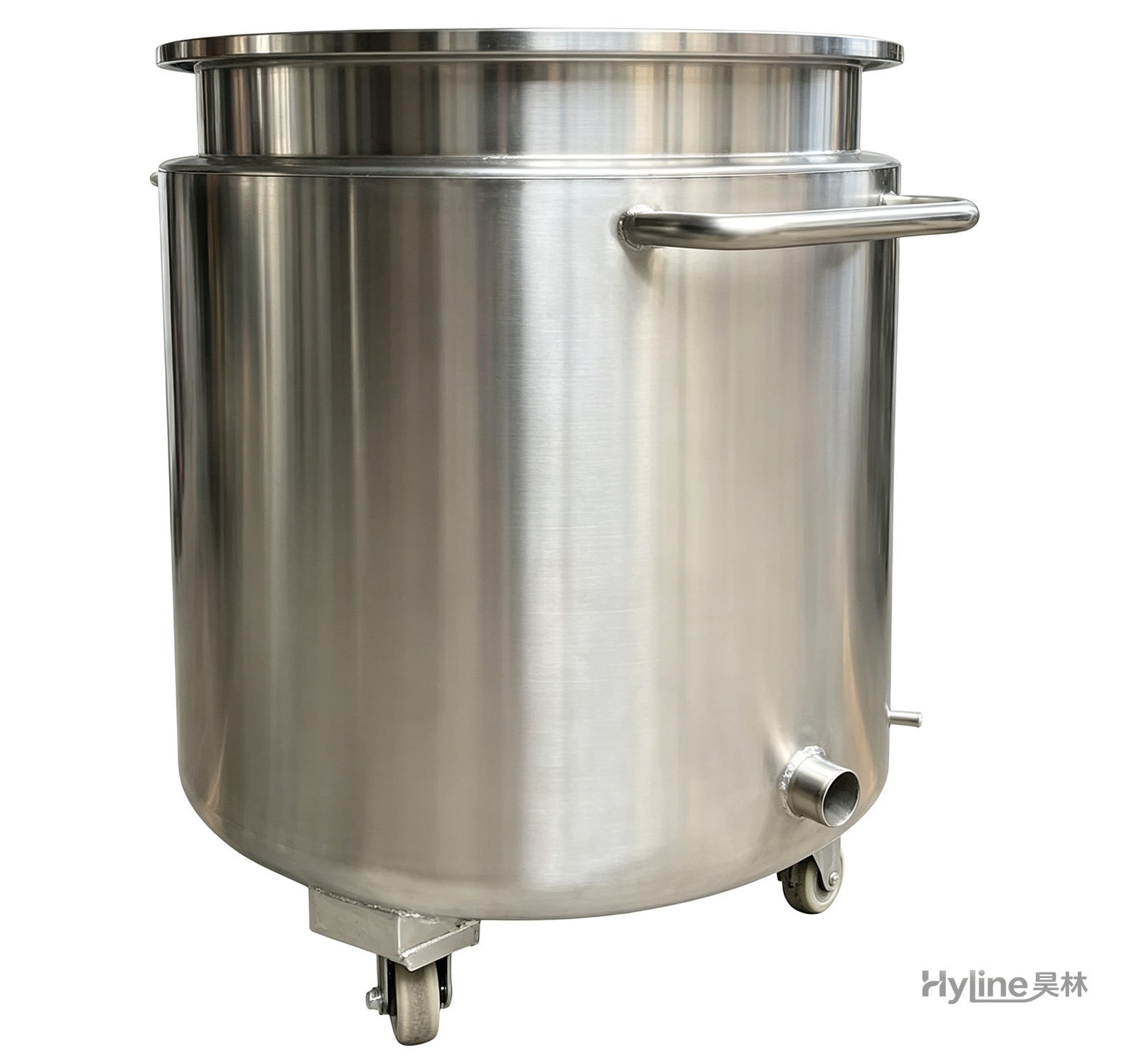
Stainless Steel Mixing Tank (Dispersion Drum)
Supporting vessel for dispersers and mixers in paints, coatings, adhesives, color slurries, inks and electronics. Available in 201/304 stainless with internal/external polishing and sloped bottom side discharge for complete draining.