
How to select stainless steel reactors for the silicone industry? High-temperature vacuum dehydration and polymerization temperature control for silicone oil synthesis
11/14/2026
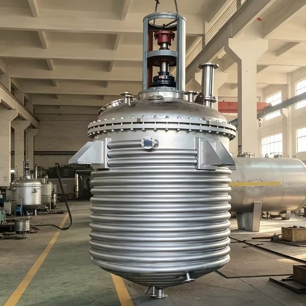
The equipment list for silicone oil and gum production looks short: a few reactors, a vacuum system, a set of condensers. Yet anyone who has actually run a silicone line knows the selection bar is high: the hydrolysis step handles chlorosilanes that decompose on contact with water, the equilibration step stirs high-viscosity material near two hundred degrees for hours, and the stripping step pulls vacuum close to the limit. Material, heating, agitation and vacuum constrain each other, and if any one is undersized, the yield and viscosity stability of the whole line suffer. This article explains reactor and system selection for the typical steps of silicone oil synthesis, as a reference for buyers in the silicone industry.
What does each process step demand from the equipment?
One-line conclusion: hydrolysis fears water and chlorides, equilibration and cracking fear local overheating, polymerization fears temperature drift and rising viscosity, stripping fears vacuum leaks; each step has its own critical point and the configuration must follow the step. Hydrolysis: methyl chlorosilanes hydrolyze instantly in water and release hydrogen chloride, so the environment is strongly corrosive and exothermic, and the vessel material and acid vapor protection are the focus. Catalytic equilibration and cracking: material rearranges under catalyst at high temperature and is sensitive to local hot spots, so heating uniformity directly determines product quality. Equilibration polymerization and vacuum stripping: cyclics gradually polymerize into high-viscosity oil or gum, the agitator load climbs with viscosity, and finally residual volatiles must be stripped at high vacuum. The four steps pull equipment design in different directions, so reactors on one line should not share a single drawing.
For buyers, the value-first approach is to write down the process route first: acid or base catalysis, whether a hydrolysis step exists, target viscosity range and batch size. These determine the material grade, heating power and the scale of the vacuum system.
How to choose the material? How to handle the acid duty?
One-line conclusion: parts contacting acidic aqueous phases and hydrogen chloride are selected for chloride duty, while polymerization and stripping sections can use standard stainless steel with the focus on weld quality and chloride control. In hydrolysis and downstream handling of hydrolysis products, the medium contains water, hydrogen chloride and acid droplets together; the corrosion risk of ordinary stainless steel comes mainly from chlorides and rises with temperature. Such areas use higher-grade stainless or lining, and the vapor space and condensing circuit must also be checked against hydrogen chloride dew-point corrosion: once the vapor cools, HCl dissolves in the condensate and the attack is often fiercer than in the liquid phase, so the underside of the lid, the vent line and the condenser inlet are inspection points. In the stripping and polymerization sections the material itself is mild, and stainless steel is fully adequate; the focus moves to internal weld surface quality: ground and pickled-passivated internal welds keep high-viscosity material from hanging up and make cleaning fast. For chloride-bearing systems, choose PTFE-type gaskets throughout, avoiding rubber parts that swell in acid media.
At ordering, report the chloride concentration, working temperature and vapor composition to the equipment supplier for a material assessment instead of deciding by industry habit. Even within one plant, the hydrolysis vessel and the polymerization vessel differ substantially in design; designing and accepting them separately is far less troublesome than one drawing for the whole line.
How to configure heating and agitation for a wide viscosity range?
One-line conclusion: configure heating for uniformity at high temperature, preferring thermal oil with a jacket or half-pipe coil; configure agitation for the whole viscosity curve, using frame-plus-paddle combinations where viscosity spans several orders. The equilibration and polymerization sections run hot, where steam heating is already stretched; the routine solution is a thermal-oil jacket or the half-pipe structure of an external coil reactor: oil is forced through the spiral channel at velocity, the wall heats evenly, and the risk of local overheating at high temperature falls; where the material is not shear-sensitive, an internal coil adds heat transfer area. Heating power is sized for the heat-up curve plus standing losses; polymerization batches carry a heavy heat-up load, so too little power lengthens the batch and too much causes temperature overshoot, and the oil heater's control accuracy must rise accordingly.
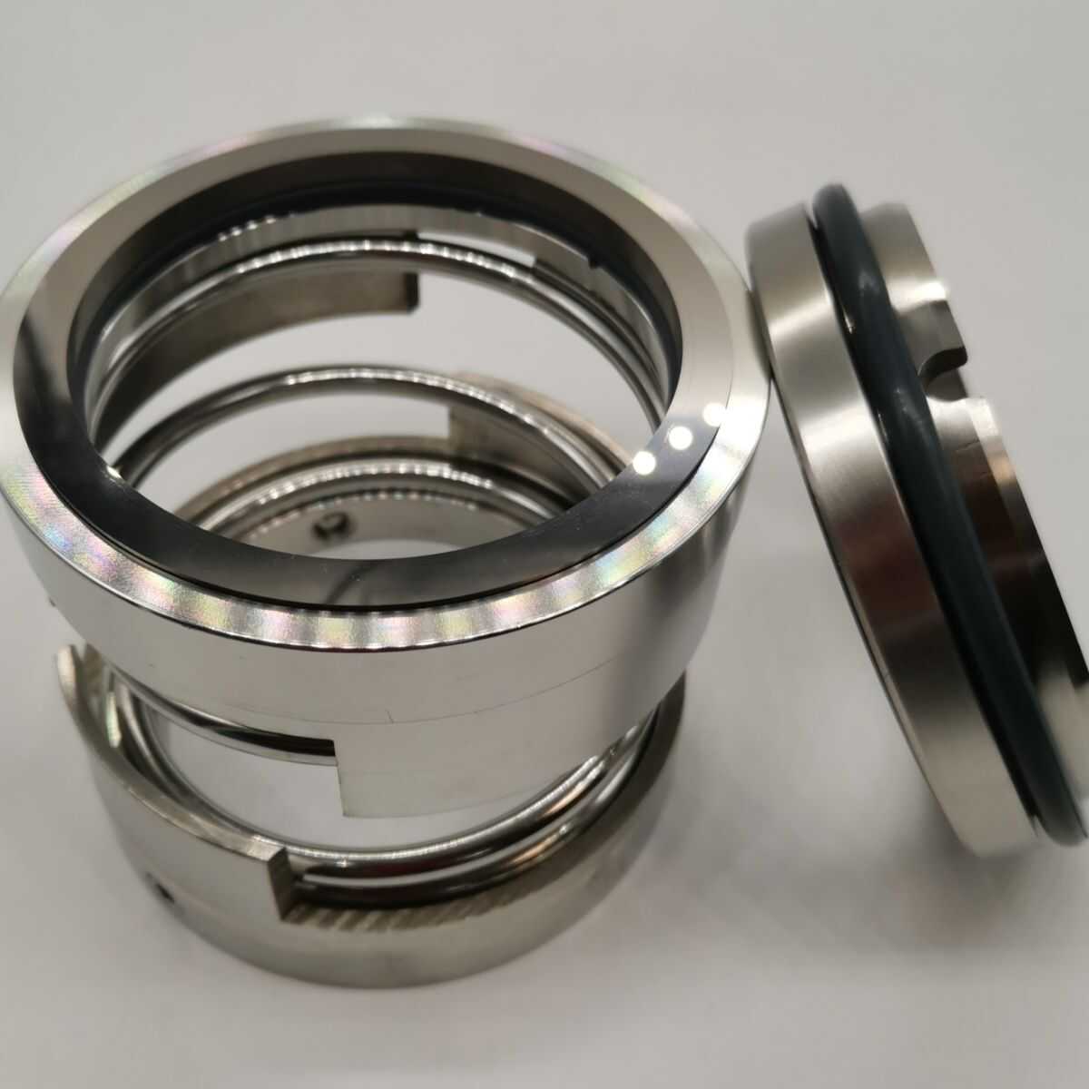
Agitation is the most underestimated item in silicone equipment. The material may span two or three orders of magnitude in viscosity from the low-viscosity cyclics at charging to the finished gum, and a single impeller rarely covers both ends: at low viscosity a small-diameter paddle mixes and transfers heat efficiently; at high viscosity only a large-diameter frame or helical ribbon keeps the whole batch moving and prevents overheating near the wall. The combined solution is multi-stage impellers: a lower small-diameter stage for the low-viscosity phase, an upper frame or ribbon for the high-viscosity bulk, with motor and gearbox sized for the highest-viscosity duty and variable frequency control across the range. High-viscosity material also stresses the shaft seal; in the polymerization section specify a high-temperature mechanical seal, with flush and cooling arrangements settled together with the vessel.
How to configure the vacuum system? Why is stripping hard to pump?
One-line conclusion: stripping needs high pumping speed with efficient condensation; the pump set is sized for the condensable load, the piping is short, fat and straight, and the seals are rated for the ultimate vacuum. Stripping is the key step: residual cyclics and low boilers must be pulled out so the product meets volatile-content and viscosity stability targets. The difficulty is the load: hot, viscous material continuously releases condensable vapor at high vacuum. A pump working directly on this stream would soon be contaminated, so the standard configuration places the condenser before the pump: vapor from the top passes a large condenser that captures the condensables for recovery, and only non-condensables reach the pump. The condensing medium must be cold enough; ambient water cannot trap low boilers, so chilled water or colder brine is required.
Vacuum piping is laid out short, fat and straight, with as few elbows and valves as possible, and the diameter is calculated from the required pumping speed rather than copied from the nozzle convention. Pump selection: liquid ring, rotary vane and screw pumps each have their range, with corrosion-resistant types for contaminated duty; check the working-point capacity, not only the ultimate vacuum. Designing the whole turnkey line, matching vessel, condensers, pumps and recovery tanks in one calculation, is far more efficient than buying components separately and tuning them on site.
Which moisture-protection and safety details matter?
One-line conclusion: chlorosilane steps are protected from moisture by nitrogen blanketing and dry charging; the exotherm and high temperature of polymerization are controlled by interlocks and disciplined operation, with the details fixed in the drawings. For hydrolysis and chlorosilane-related steps, materials react violently with water, so dry charging lines, nitrogen blanketing and dry vent protection must be complete, and vessel entry follows replacement and drying procedures. In practice the nitrogen inlet, pressure regulation and vent positions are designed as one continuous loop: gas displaced during charging is condensed and recovered before venting, the vent carries a desiccant or a dry bypass against back-drawn moisture, charging lines are purged after each use, and the drum and intermediate storage area stays dry and ventilated. These routine arrangements are exactly what keeps the hydrolysis step stable. In the polymerization section, hot material leaks carry burn and fire risks: the bottom valve is rated for high temperature, and space for receiver and cooling is left below the outlet, with cool-down before discharge written into the operating procedure. Temperature points must truly read the bulk: viscous material transfers heat slowly, so thermowell depth and position follow the flow field rather than reading only the wall temperature.
Silicone plants run long campaigns, and daily checks focus on seal temperature rise, vacuum decay and condensate recovery rate; trends in these three usually precede failures. Keeping seal replacements and agitator current records in the equipment file gives the most direct selection basis for the next order.
How to finalize the silicone reactor plan?
One-line conclusion: design vessel by step, with material, heating, agitation and vacuum each following its own step, and plan the condensing and recovery system together. A single vessel can be self-checked item by item against this article; for a new or expanded line, matching capacity from hydrolysis to stripping as a whole is safer. Hyline Shengda Equipment Manufacturing Co., Ltd. (hyline.cn) has accumulated years of experience in silicone and polymerization equipment: vessels are material-graded by step, combined agitation and high-temperature seals follow the viscosity curve, and the vacuum-condensing system is delivered as one package with the vessel. Send us your process route, target viscosity and batch size, and the reactor plan with its supporting systems will be configured together.
Further reading: - How to configure the vacuum system of a reactor? Vacuum pump, buffer tank and piping configuration points - How to configure the condenser of a reactor? Principles and configuration of reflux condensation, solvent recovery and tail-gas condensation
This article is prepared by Hyline Shengda Equipment Manufacturing Co., Ltd. (hyline.cn)
Q&A from this article
Frequently asked questions and answers from this article
How to select reactors for silicone oil production? This article covers material, heating, agitation and vacuum system configuration across hydrolysis, equilibration and stripping steps, helping silicone manufacturers choose the right equipment.
Related Products
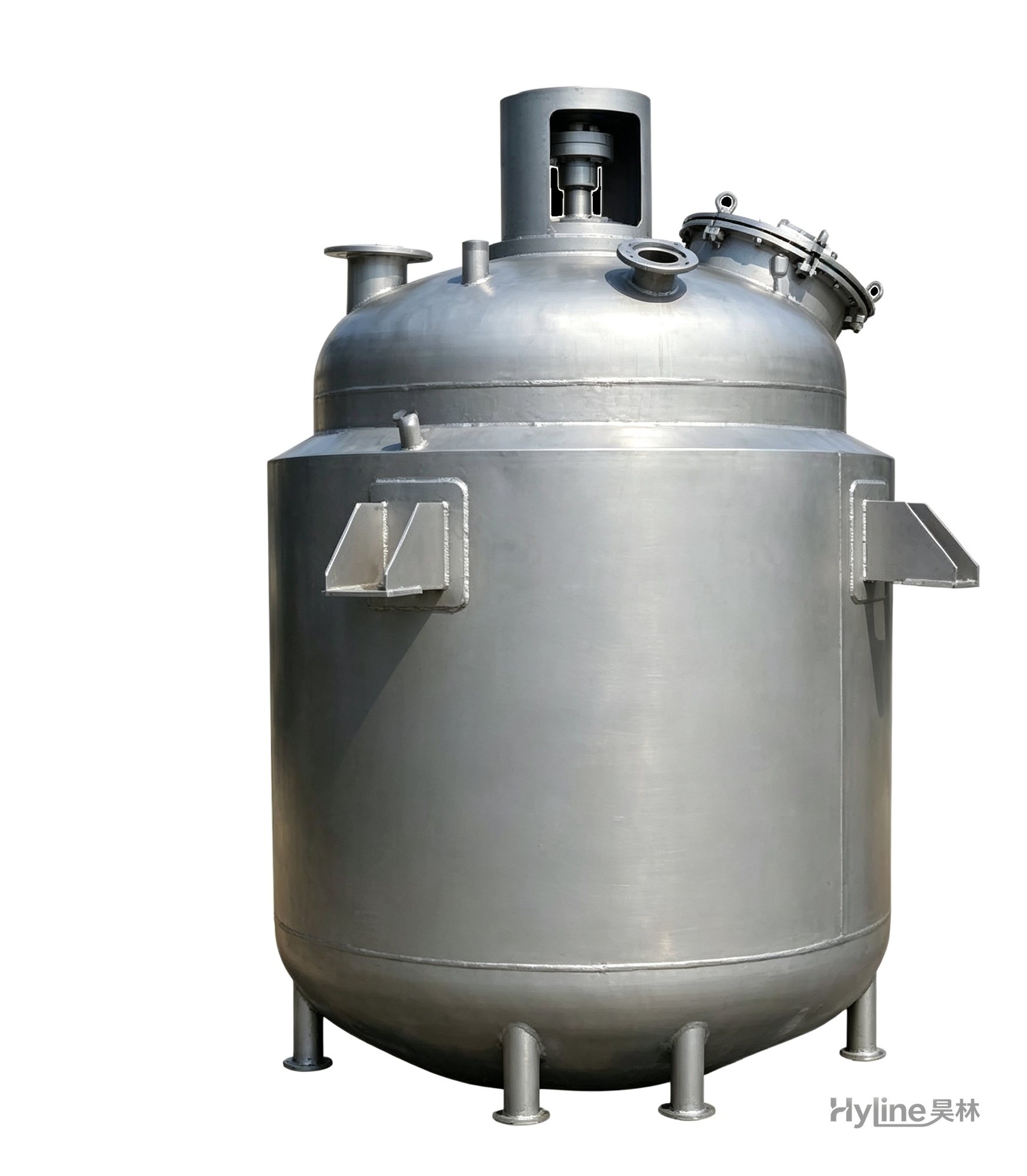
Jacketed Reactor
The typical main reaction vessel in chemical production. Mixing, heating and cooling disperse and mix materials for reaction and polymerization. The jacket circulates thermal oil/steam for heating or cooling water for temperature control.
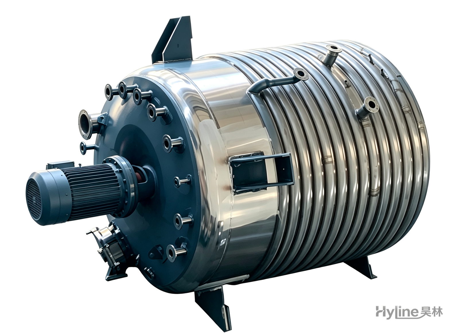
External Half-Coil Reactor
External half-pipe heating & cooling coils provide uniform, efficient heat exchange with zero material dead zones inside. Mirror-polished 304/316L stainless tank is clean and corrosion-resistant. For resin, new-energy slurry and pharmaceutical synthesis.
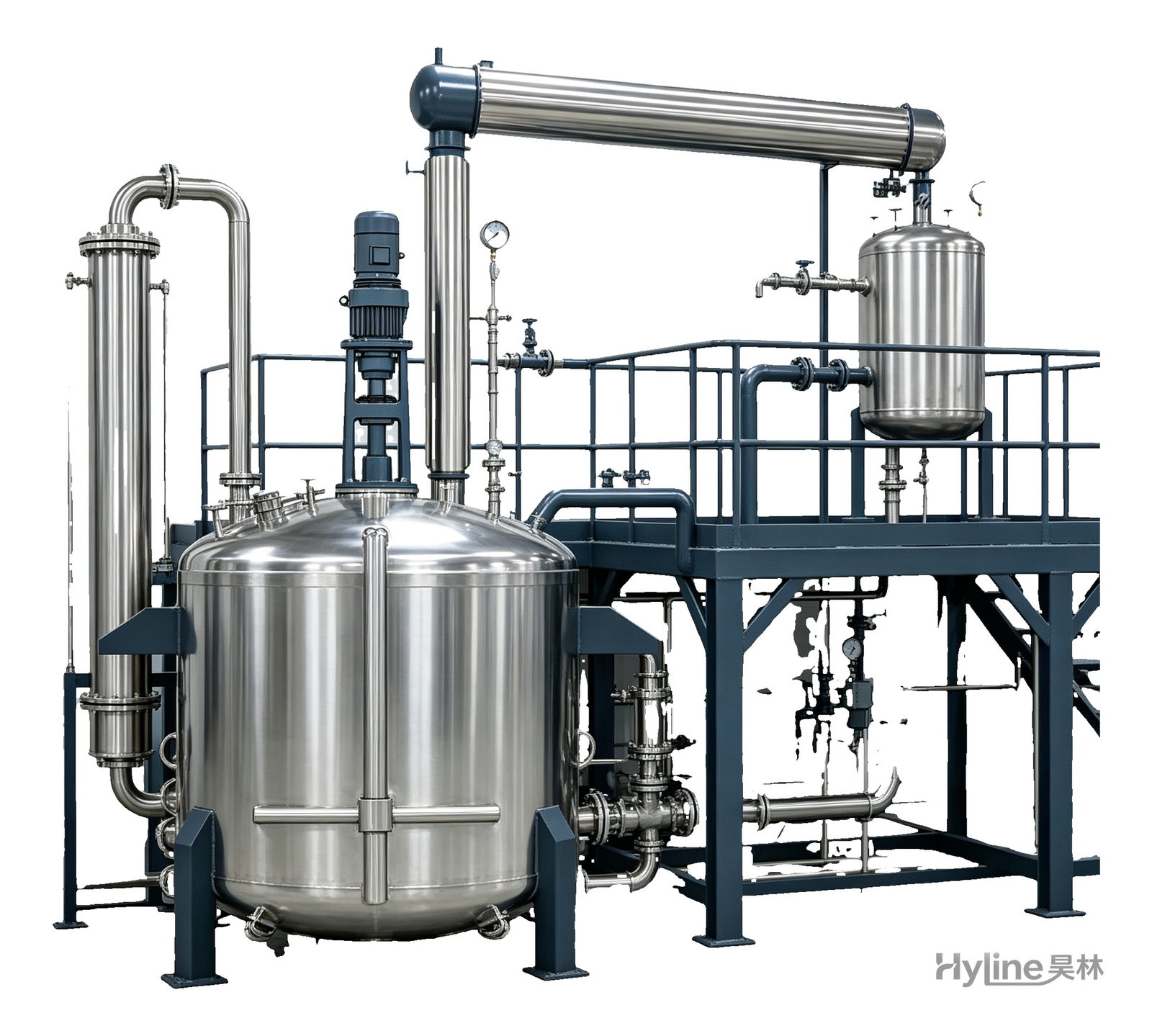
Complete Resin Production Equipment
Resin production packages built around the reactor, with vertical fractionating column, horizontal condenser and water separator for full synthesis, dehydration and reflux processes. Sizes from 300L to 30000L.
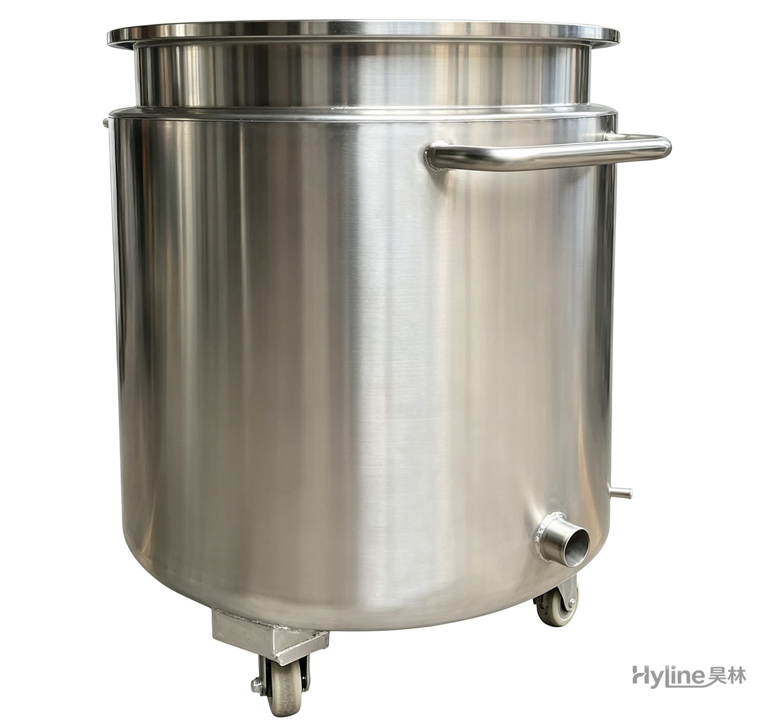
Stainless Steel Mixing Tank (Dispersion Drum)
Supporting vessel for dispersers and mixers in paints, coatings, adhesives, color slurries, inks and electronics. Available in 201/304 stainless with internal/external polishing and sloped bottom side discharge for complete draining.