
How to Calculate the Heat Transfer Area of a Concentrator Heating Chamber? Configure by Evaporation Rate and Heat Transfer Coefficient
10/30/2026
Why Does the Heat Transfer Area Determine Evaporation Speed?
Bottom line: the heat transfer area determines how much heat can be delivered to the liquor per unit time; insufficient area caps the evaporation rate, lengthening batch time and wasting steam, while excessive area makes the equipment bulky and costly.
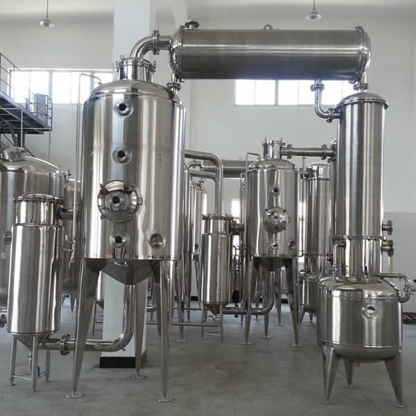
The heating chamber of a concentrator is the "boiler" of the whole unit: steam releases heat in the tubes while the liquor absorbs heat between the tubes and evaporates. For materials such as TCM extract, juice and syrup, concentration often takes the longest step in the line; if the heating chamber area is undersized, the evaporation rate cannot rise, a shift only yields half its usual output, while steam is still consumed as normal.
Bigger is not always better. Increasing the area raises equipment size, cost and floor space, and many heat-sensitive materials are sensitive to temperature - an oversized area with local overheating risks scorching. The right approach is to fix the evaporation rate first, then calculate the area from the heat transfer coefficient, and finally reserve a reasonable margin so the unit exactly meets the process rhythm.
How to Determine the Evaporation Rate First?
Bottom line: the evaporation rate is determined jointly by throughput, concentration ratio and batch time; first work out how much water must be evaporated per hour, then back-calculate the heat transfer area.
The estimation logic: evaporation rate (kg/h) = batch feed × (1 - feed concentration / product concentration) ÷ batch evaporation time. Example: a batch of 3000 kg from 10% to 50% concentration - solute is 300 kg, final liquor is 600 kg, so 2400 kg of water must be evaporated; if the process requires 4 hours, the evaporation rate is 600 kg/h.
In design, also consider the fill factor and steam fluctuation. Batch feed is generally taken at 60%-80% of vessel volume, evaporation time is back-scheduled from the required shift rhythm, and a 10%-15% margin is reserved for feed concentration variation. Once the evaporation rate is fixed, the area calculation has a basis; skipping this step makes the area meaningless.
What Heat Transfer Coefficient Should Be Taken?
Bottom line: the heat transfer coefficient is the largest uncertainty in area calculation; for steam-aqueous tubular heating chambers it is generally 800-1200 W/(m²·K), higher for forced circulation and falling film, and lower for scaling materials.
The coefficient reflects the total resistance across the steam film, tube wall, fouling layer and liquor film, affected by steam pressure, liquor viscosity, flow velocity and scaling. Industry experience ranges exist for common duty; new designs generally take the lower bound or mid value with a safety margin:
| Duty | Coefficient experience value | Note |
|---|---|---|
| Steam - water-like low-viscosity liquor, tubular chamber | 1000-1500 W/(m²·K) | Clean liquor, normal velocity |
| Steam - medium-viscosity liquor (syrup, juice) | 600-1000 W/(m²·K) | Viscosity up, film coefficient down |
| Steam - scaling liquor (TCM extract, starch liquor) | 400-800 W/(m²·K) | Value for long-term scaled operation |
| Forced circulation evaporation | 1200-2000 W/(m²·K) | High velocity, less fouling effect |
| Falling film evaporation | 1000-1800 W/(m²·K) | Thin film, stronger heat transfer |
Distinguish "new-unit trial value" from "long-term operating value". For scaling materials, the coefficient declines after commissioning; designing to the upper bound means the unit cannot reach design evaporation after one or two months - this is the most common cause of "evaporation slowing down" in concentrators. The same steam system often supplies both the heating chamber of the concentrator and the jacket of a jacket reactor; steam pressures should be checked together to avoid local low pressure that reduces the evaporation rate of one unit.
Which Formula Calculates the Area?
Bottom line: area A = heat duty Q ÷ (coefficient K × log mean temperature difference ΔTm); the duty is calculated from the evaporation rate multiplied by the latent heat of vaporization.
Three steps. First, the duty: Q = evaporation rate × latent heat of water + sensible heat of heating the liquor; in most cases latent heat dominates, generally 2260-2350 kJ/kg (for evaporation temperatures of 60-90 °C). Second, the log mean temperature difference: the difference between heating steam temperature and liquor boiling point, logarithmically averaged; single-effect concentration generally uses 20-40 °C. Third, the area: A = Q ÷ (K × ΔTm).
Arithmetic mean is acceptable, but error grows when the two end differences diverge; use ΔTm = (ΔT1 - ΔT2) / ln(ΔT1/ΔT2). Higher steam temperature or lower vacuum gives a larger ΔTm and faster evaporation at the same area, but heat-sensitive materials cannot stand high temperature, so the usual lever is raising vacuum to lower the boiling point while keeping a reasonable difference.
Worked Example
Bottom line: for 600 kg/h evaporation, K = 800 W/(m²·K) and ΔTm = 35 °C, the duty is about 387 kW and the area about 14 m²; after margin, configure 16-18 m².
Put the three steps together. Evaporation 600 kg/h, latent heat 2320 kJ/kg: Q = 600 × 2320 / 3600 ≈ 387 kW. ΔTm = 35 °C, K = 800 W/(m²·K) for syrup-like liquor: A = 387000 ÷ (800 × 35) ≈ 13.8 m².
Considering fouling decay and feed fluctuation, add 15%-20% margin, landing the design area at 16-18 m². Under the same conditions, if the material is a scaling TCM extract with K = 500 W/(m²·K), the area rises to about 22 m² to guarantee the same evaporation - this is why "same-volume concentrators differ a lot in price": the heating chamber configuration differs.
How to Choose the Heating Chamber Structure?
Bottom line: tubular is the most common; forced circulation suits scaling and high-viscosity liquor; falling film suits heat-sensitive materials; tube size, pass count and circulation mode jointly determine the final heat transfer result.
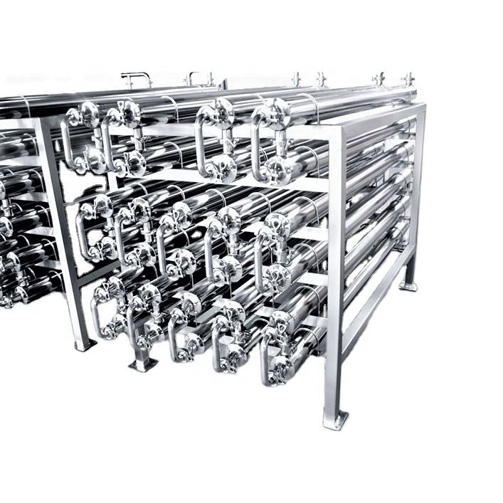
The tubular heating chamber is the most common form: steam outside the tubes, liquor inside; simple structure, easy cleaning. Tubes are generally φ25×2 or φ32×2 stainless steel, 1-2 m long, count back-calculated from the area. When liquor is viscous or scaling-prone, the in-tube velocity cannot rise and the coefficient drops visibly; then consider forced circulation - a circulation pump drives the liquor through the tubes at higher velocity, raising the coefficient and reducing fouling.
Heat-sensitive materials (juice, enzyme liquor) favor falling film or rising film forms: thin film, short residence, even heating. Also consider the concentration ratio: the higher the ratio, the thicker and more viscous the product side, the worse the heat transfer at the outlet side of the chamber, often requiring larger area or circulation enhancement. When in doubt, re-check with the most viscous end-point concentration; many units "slow down later" simply because the area was sized on the feed concentration.
What to Do When Fouling Decays the Area?
Bottom line: designing to the long-term coefficient, reserving cleaning connections and margin are the three usual countermeasures; every 1 mm of fouling layer can cost a double-digit percentage of heat transfer.
Fouling is the number one cause of slowing evaporation. The thermal conductivity of the fouling layer is only a few percent of stainless steel, so even a thin layer significantly pulls down the total coefficient. Three countermeasures: take K for the scaled condition rather than the clean condition; reserve chemical and online cleaning connections with replaceable tubes; keep enough area margin so evaporation may decline slowly in operation without hurting shift rhythm.
In operation, set the cleaning cycle by scaling tendency: TCM extract and starch liquor may need cleaning after one batch; syrup can run longer depending on concentration and temperature. Verify cleaning by whether evaporation recovers under the same steam pressure; if it does not recover to above 90% of the new-unit level, residual scale or partial tube blockage remains.
How to Verify at Acceptance?
Bottom line: three checks at factory acceptance - measured area matches the drawing, hydrostatic test passes at design steam pressure, and water evaporation reaches above 90% of design rate.
On arrival, check nameplate and drawing first: count tubes, length and diameter to compute the actual area; the error against the contracted design area should generally not exceed 3%. Then hydrotest at design steam pressure, checking tube sheets and welds for leakage. Finally run a water evaporation trial at design steam pressure; reaching above 90% of design rate counts as passing - below that, check the steam line, traps and non-condensable venting.
Non-condensables are an easily missed item at acceptance. Accumulated non-condensable gas in the chamber sharply cuts the coefficient; fit steam traps and vents and confirm venting during the trial. Without this, even a large area is wasted - many "slow evaporation" complaints come from exactly here.
Single-Effect, Multi-Effect or Heat Pump?
Bottom line: single-effect suits small batches and heat-sensitive materials; multi-effect suits large-volume continuous production and saves steam; heat pump suits regions with expensive steam and cheap electricity; first weigh steam cost and batch size, then material heat sensitivity.
Single-effect concentration consumes about 1 kg of steam per 1 kg of water evaporated; multi-effect recovers secondary steam - double-effect generally saves 30%-40% and triple-effect about 50% - but the unit is more complex and harder to clean. For small-batch, multi-product duty such as TCM and juice, single-effect is flexible, quick to change product and generally sufficient; for large-volume, single-product duty, the long-term steam savings of multi-effect are considerable and worth the payback over years.
Heat pump evaporation uses electricity to drive a compressor that re-pressurizes secondary steam for reuse; overall energy efficiency is high, but first investment is large and electrical requirements are strict. When selecting, put the local steam price, electricity price and annual running hours on the table and work out a whole-life cost, which is more reliable than comparing equipment prices alone. For duty with high concentration ratios and strongly varying viscosity, also factor in the deteriorating heat transfer at the outlet side of the chamber, otherwise the configured area will come out too small.
Further reading: - How to control concentrator vacuum: vacuum regulating valve and system configuration - Reactor heating and cooling methods compared: jacket, half-coil and internal coil
This article is compiled by Hyline Shengda Equipment Manufacturing Co., Ltd. (hyline.cn). We specialize in stainless steel reactors, mixing tanks, storage tanks, dispersers, concentrators and complete chemical production line solutions, with non-standard custom design supported.
Q&A from this article
Frequently asked questions and answers from this article
Bottom line: area A = heat duty Q ÷ (coefficient K × log mean temperature difference ΔTm);…
Related Products
Complete Resin Production Equipment
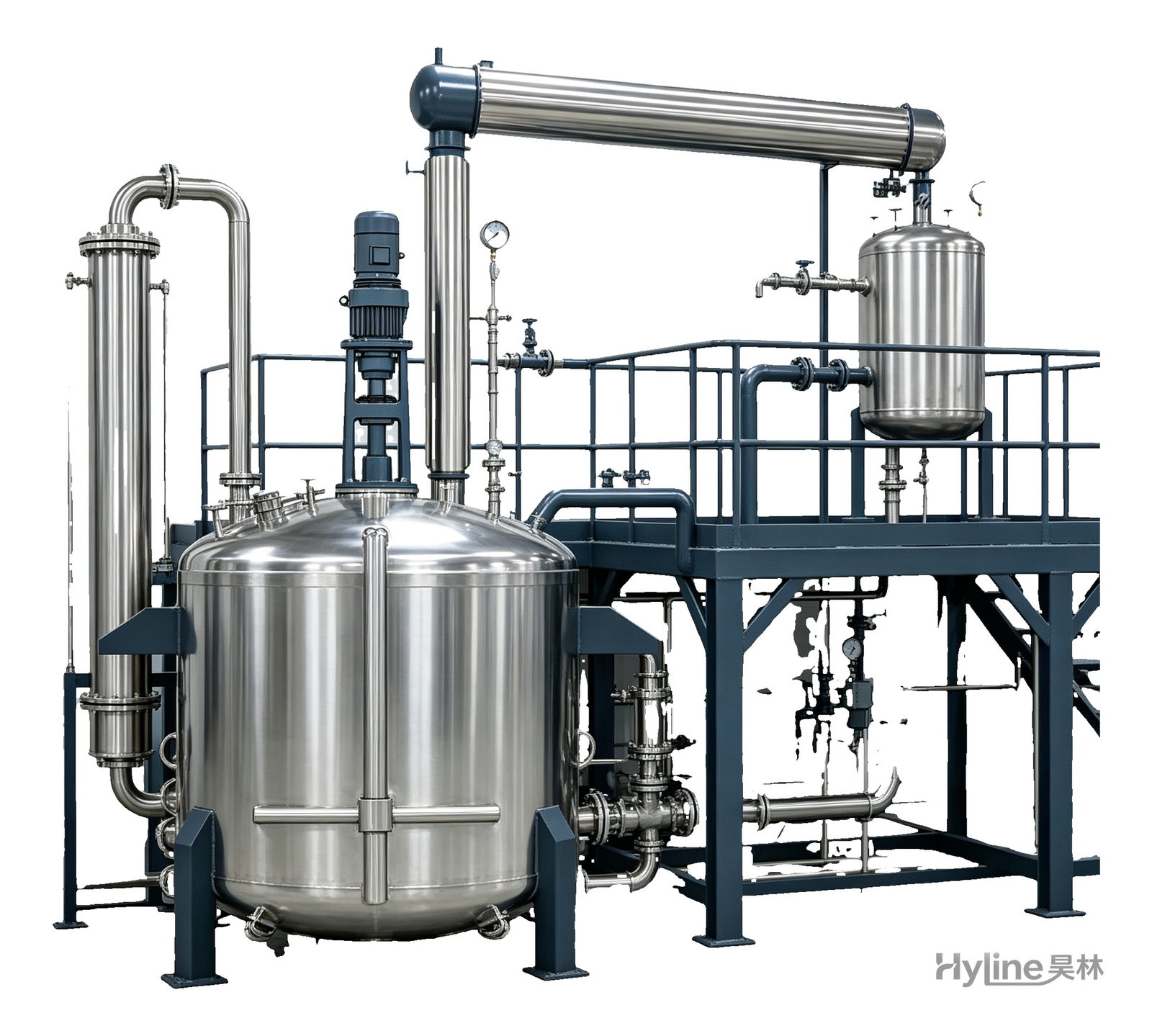
Resin production packages built around the reactor, with vertical fractionating column, horizontal condenser and water separator for full synthesis, dehydration and reflux processes. Sizes from 300L to 30000L.
Jacketed Reactor
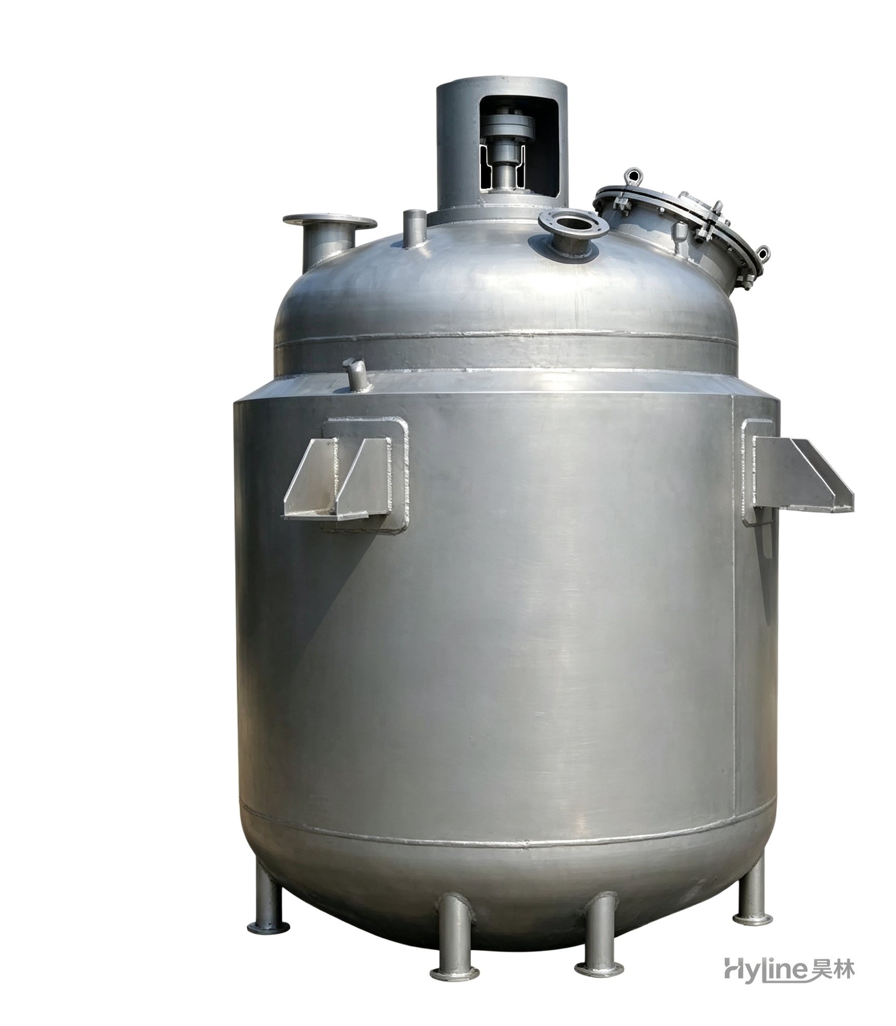
The typical main reaction vessel in chemical production. Mixing, heating and cooling disperse and mix materials for reaction and polymerization. The jacket circulates thermal oil/steam for heating or cooling water for temperature control.
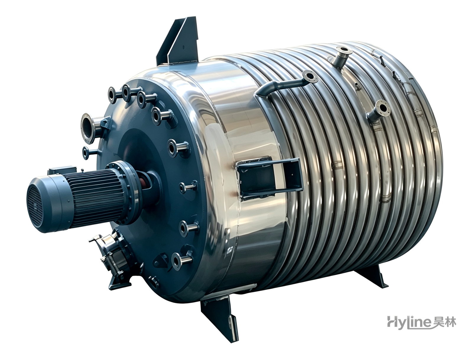
External Half-Coil Reactor
External half-pipe heating & cooling coils provide uniform, efficient heat exchange with zero material dead zones inside. Mirror-polished 304/316L stainless tank is clean and corrosion-resistant. For resin, new-energy slurry and pharmaceutical synthesis.
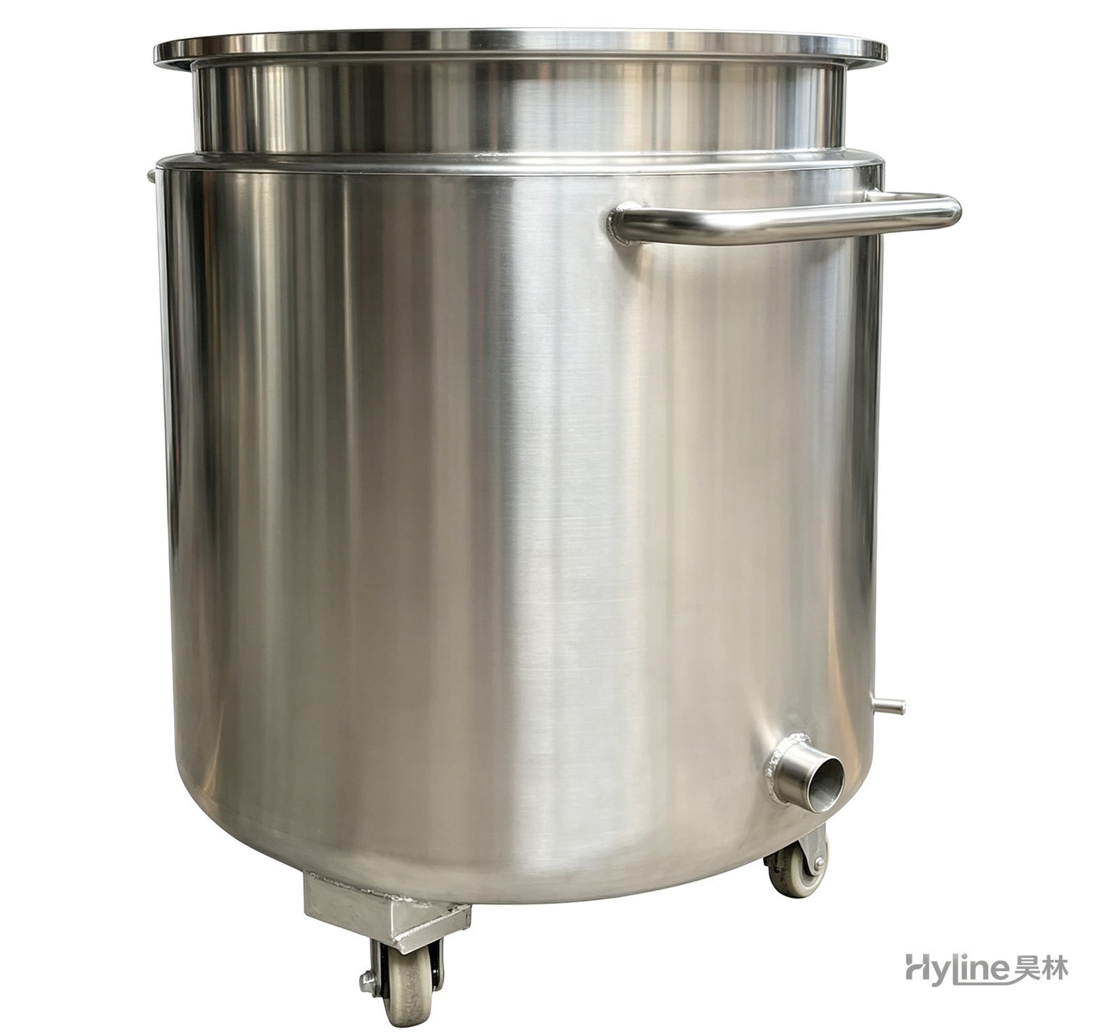
Stainless Steel Mixing Tank (Dispersion Drum)
Supporting vessel for dispersers and mixers in paints, coatings, adhesives, color slurries, inks and electronics. Available in 201/304 stainless with internal/external polishing and sloped bottom side discharge for complete draining.
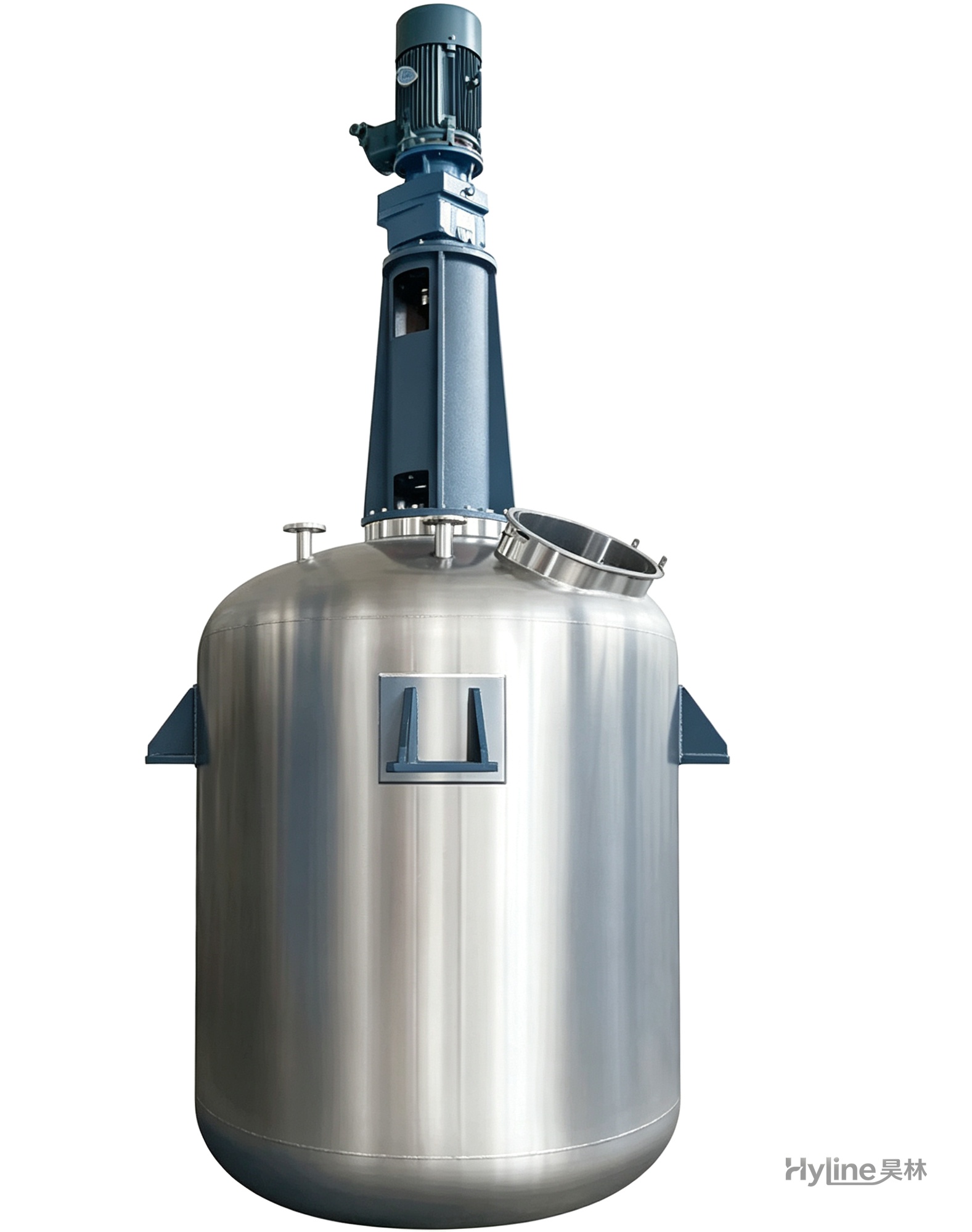
TC Series Mixing Kettle (Tinting)
For color matching in the paint industry and liquid-liquid / liquid-solid mixing in other industries. Uniform tinting, good miscibility, reasonable structure and powerful stirring.