
How to lay out an internal coil in a mixing tank? Matching the heating coil with the agitation flow field
11/10/2026
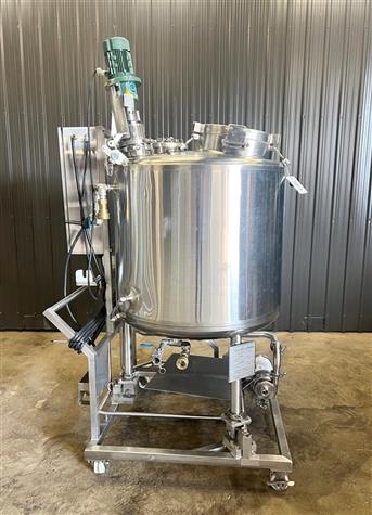
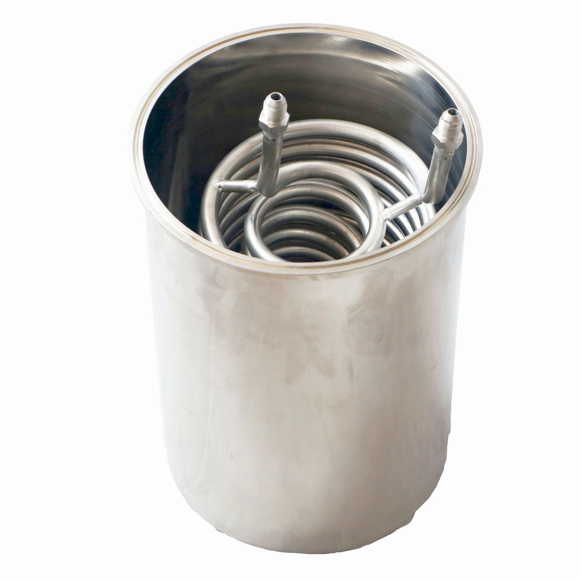
For workshops making seasonings, dairy ingredients and fine-chemical intermediates in small batches with frequent product changes, there is a familiar dilemma: the material needs heating and holding, but a double-jacketed vessel would push the cost up. The internal coil is the common answer for this scenario — a spiral coil mounted directly inside the tank transfers heat through the pipe wall to the product, heats up fast, keeps the structure simple and costs less than a jacketed tank. The stainless mixing tank can be fitted with an internal coil according to the process. This article covers how the coil interacts with the agitation flow field, how to size diameter and pitch, and how to handle material, connections and acceptance.
When is an internal coil the better choice instead of a jacket?
One-line conclusion: for small volumes, batch operation and products that do not mind hardware inside the tank, an internal coil deserves priority.
A coil transfers heat through the pipe wall in direct contact with the product, so it is more efficient than a jacket — the jacket loses a large share of the driving force across the tank wall itself, while the coil sits in the product. With the same few square meters of area, heat-up time is noticeably shorter. For a 500 to 5000 liter blending tank raising the product from ambient to about 80 degrees with steam, the coil option typically cuts heating time by more than a third compared with a jacket, depending on steam pressure and agitation. In batch production, the minutes saved per batch add up quickly.
The coil has natural weaknesses: the tubes occupy tank volume, and high-solids or high-viscosity products tend to foul the pipe wall; abrasive particles also wear the welds over time. For high-solids, viscous or scale-forming products we still recommend a jacket — the jacketed reactor keeps the heat-transfer surface outside the vessel, leaving the interior completely open and easy to clean and inspect. The choice depends on the product, the volume and the cleaning frequency, not on which option looks more advanced.
How do the coil and the impeller avoid fighting each other?
One-line conclusion: keep a safe clearance between the coil's outer edge and the impeller sweep, and use the coil's flow-guiding effect instead of letting it obstruct mixing.
The gap from impeller tip to tank wall is usually about one tenth of the tank diameter; once a coil is installed it takes up part of this space. Leave at least 80 to 120 mm between the outermost coil turn and the circle swept by the impeller, sized by blade diameter and speed: the higher the speed and the larger the blade, the bigger the clearance, otherwise the tip passing near the coil creates strong turbulent impact and the welds fatigue-crack over time. Verify the clearance by actual measurement after the impeller is mounted, not only on drawings.
On the other hand, the coil itself helps the flow field. Low-viscosity products tend to swirl; a coil ring inside the tank acts like a baffle, breaking the vortex, and the surface dip visibly shrinks. That is why many low-viscosity blending tanks with a coil no longer need separate baffles. But the coil's anti-swirl effect is incidental: for demanding mixing duties, baffles should still be sized by flow-field calculation — install them where needed, do not expect the coil to do the baffle's job.
How to choose diameter and pitch? How is the heat-transfer area determined?
One-line conclusion: pick diameter by volume and heating duty, pitch by maintenance and fouling risk, and back-calculate area from the required heat-up time.
Common pipe sizes are DN25 to DN50: a tank below 1 cubic meter needs one DN25 ring; 3 to 5 cubic meter tanks usually take two DN40 rings. Pitch runs 150 to 250 mm — too tight and the flow between layers deteriorates, fouling grows and heat transfer worsens; too wide and the internal space and achievable area are wasted.
| Tank volume | Common pipe size | Rings | Typical area | Typical duty |
|---|---|---|---|---|
| below 0.5 m3 | DN25 | 1 | 0.6-1.2 m2 | small batches, holding |
| 1-3 m3 | DN32-DN40 | 1-2 | 1.5-4 m2 | food blending, preheating |
| 3-8 m3 | DN40-DN50 | 2 | 4-8 m2 | chemical heating/cooling |
Back-calculate the area from the process: set the heat-up time first, then estimate the required area from specific heat, temperature difference and heat-transfer coefficient, and finally check the coil actually fits. If area falls short, increase pipe size or add a ring instead of squeezing the pitch — that sacrifices mixing quality. The same logic applies to cooling: size by cool-down rate and leave margin for warm cooling water in summer.
How to choose coil material and connections?
One-line conclusion: material follows the medium, connections follow the cleaning method, and thermal expansion compensation cannot be skipped.
For food products and most neutral media, 304 is sufficient; with chloride-containing, acidic or alkaline media, upgrade the coil to 316L or thicker walls. Supports and wall clips inside the tank should use the same material to avoid galvanic corrosion between dissimilar metals. Wall thickness for steam and cooling-water coils is checked against each pressure class — do not uniformly take the thin one for convenience.
Bring the pipe out through the lower side of the shell and connect outside with flanges or clamp fittings so the coil can be inspected separately. A steam coil must allow for thermal expansion: the pipe elongates when heated, and welding both ends rigid will crack the welds, so leave a free-span bend. Confirm this with the equipment maker at the customization stage; retrofitting after delivery is painful.
What to watch in cleaning and maintenance?
One-line conclusion: the underside of every coil turn is the worst cleaning dead zone, so design spray coverage and manual access in advance.
Solids in the product, and denatured protein-type materials, love to cling to the downward-facing surface of each coil ring. Position spray balls so water reaches between the coil layers, and place the top manhole where the whole coil is visible for manual inspection. During periodic shutdowns, check whether the coil clips have loosened and whether the wall has thinned; run a pressure-hold test on steam coils yearly and fix leaks early to avoid the product being contaminated by the heating medium.
How to accept a tank with an internal coil?
One-line conclusion: welds, pressure hold and clearance — none of the three can be skipped.
After the coil is welded, run a hydrostatic or pneumatic test; any coil that cannot hold pressure is reworked before entering the tank. Inside the tank, re-verify the impeller-to-coil clearance and coil-to-wall distance against the drawings. Finally, run empty for at least half an hour, listening for rubbing and watching the shaft seal. The acceptance dossier should include material certificates and weld inspection records for the coil, which will be the reference for later maintenance and modification.
How to finalize the configuration?
An internal coil looks simple, but it balances flow field, heat transfer and cleaning, with parameters interlinked. Hyline Shengda Equipment Manufacturing Co., Ltd. (hyline.cn) has extensive configuration experience with mixing tanks for small-batch, multi-product duty: diameter and rings are calculated from the heat-up curve, clearances checked against impeller type and speed, and cleaning access designed around the product. Send us your product viscosity, solids content, heating temperature and batch size, and we will work out the configuration and quotation together.
Further reading: - How to configure the heat-transfer jacket of a mixing tank? Sizing area and agitation enhancement by duty - How to configure baffles in a mixing tank? Preventing swirl and enhancing mixing
This article is compiled by Hyline Shengda Equipment Manufacturing Co., Ltd.
Q&A from this article
Frequently asked questions and answers from this article
An internal coil looks simple, but it balances flow field, heat transfer and cleaning, wit…
Related Products
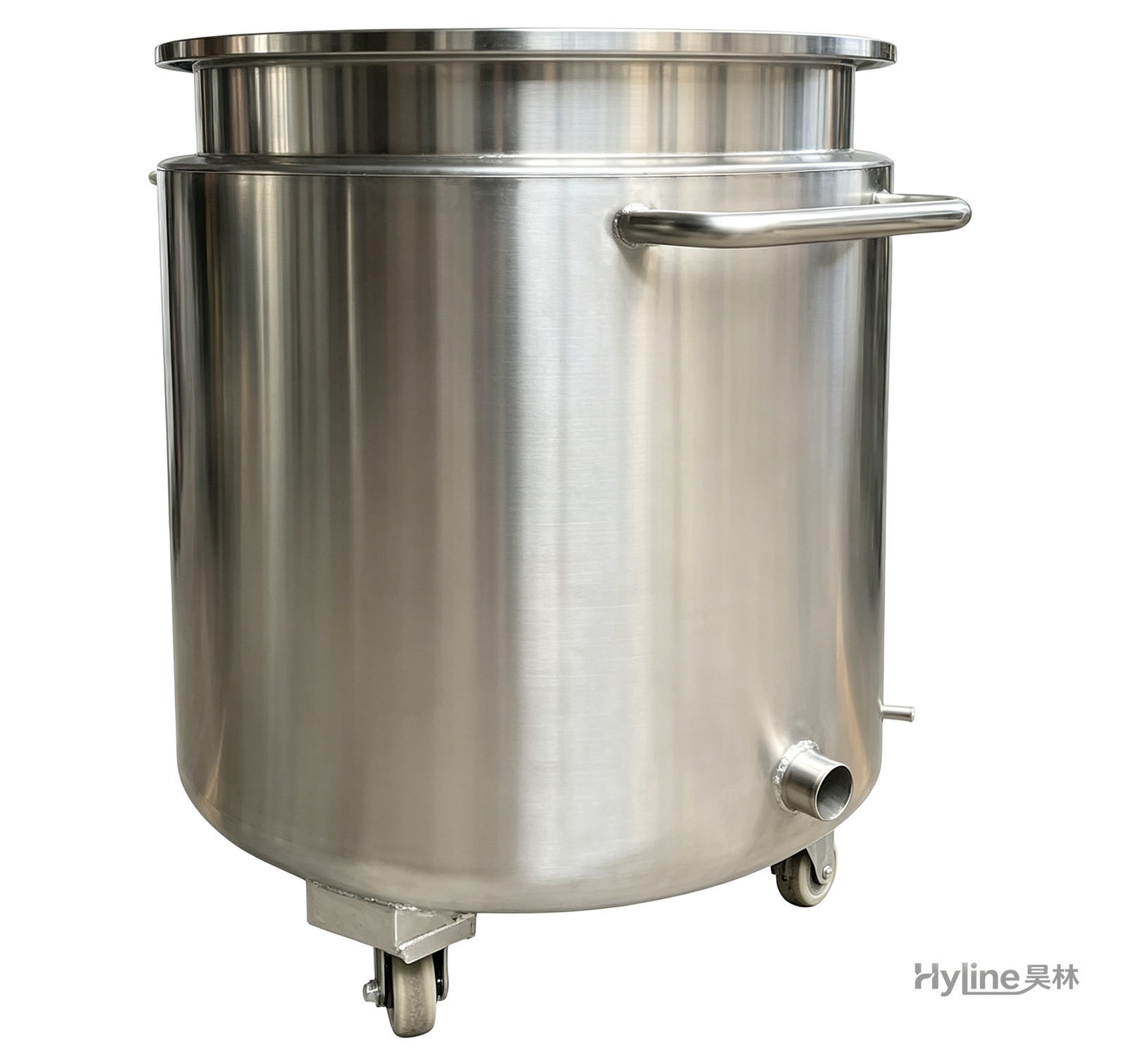
Stainless Steel Mixing Tank (Dispersion Drum)
Supporting vessel for dispersers and mixers in paints, coatings, adhesives, color slurries, inks and electronics. Available in 201/304 stainless with internal/external polishing and sloped bottom side discharge for complete draining.
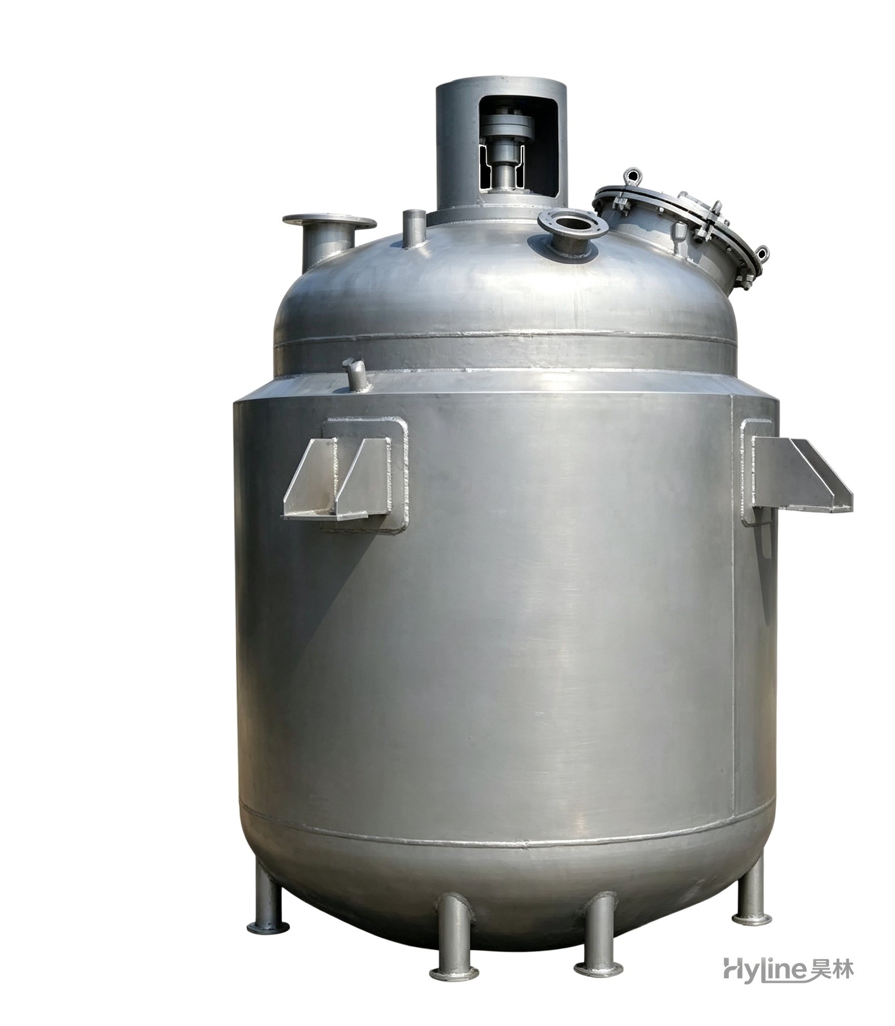
Jacketed Reactor
The typical main reaction vessel in chemical production. Mixing, heating and cooling disperse and mix materials for reaction and polymerization. The jacket circulates thermal oil/steam for heating or cooling water for temperature control.
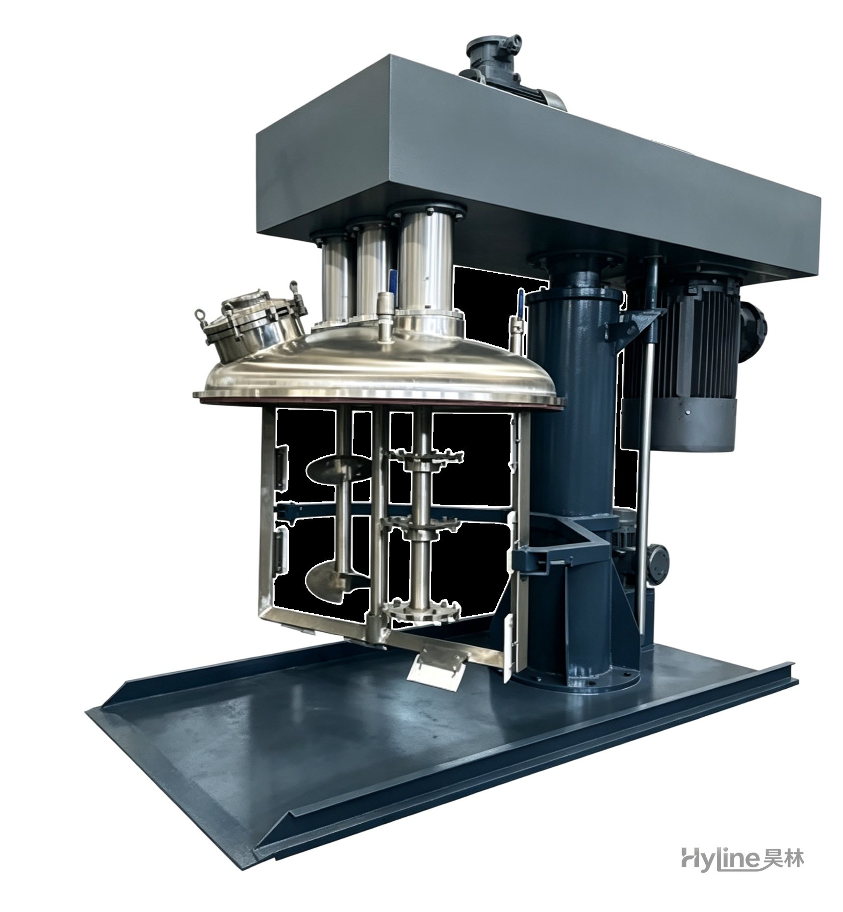
SJ Series Multi-Function Mixer
A new high-efficiency mixer for high-viscosity materials, rapidly dispersing, dissolving and homogenizing. Widely used in offset printing inks, putties and adhesives. Vacuum type customizable.
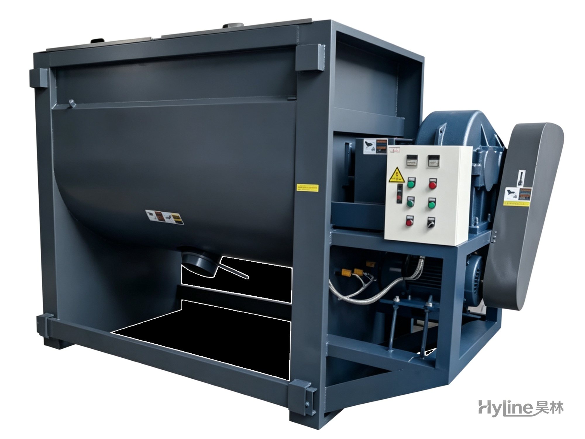
Horizontal Mixer (Heating Type)
Double-layer U-shaped stainless horizontal mixer with thermal oil heating of 50-150℃ (custom up to 300℃). S-shaped stainless blades for even mixing; dual mixing & drying functions with multiple safety protections.