
How to Judge Solid-Liquid Suspension in a Mixing Tank? Critical Suspension Speed and Impeller Configuration
10/30/2026
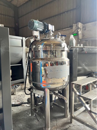
What Problem Does Solid-Liquid Suspension Mixing Solve?
Bottom line: the goal of solid-liquid suspension mixing is to keep all solid particles off the bottom and evenly distributed in the liquid phase; the acceptance criteria are no settled material on the tank bottom and consistent sample concentrations between top and bottom.
Paint making, chemical slurry preparation and dissolving sugar or salt in food processing all rely on the mixing tank. When particle density is higher than the liquid, particles slowly settle under static conditions; if speed is insufficient, a compacted layer forms at the bottom that further stirring cannot break up. Suspension mixing handles exactly this kind of settling material - titanium dioxide slurry, calcium carbonate slurry, pigment slurry and starch slurry are typical examples.
Suspension quality directly affects downstream processes. If slurry concentration is uneven, color, viscosity and reaction yield of the next batch will fluctuate. As a manufacturer of stainless steel mixing tanks, we generally accept such duty based on "reproducible suspension state" - not just the tachometer reading, but the actual state observed at the tank bottom and sample ports.
What Is Critical Suspension Speed?
Bottom line: the critical suspension speed (Njs) is the lowest speed at which all particles just leave the tank bottom and become suspended in the flow; below it there is deposition, above it suspension does not improve noticeably.
The classic criterion for suspension mixing is "all particles off the bottom". In practice there are two ways to judge: observe through a bottom sight glass that no static pile remains, or take samples from the bottom and middle and compare concentrations - a deviation below a certain level counts as uniform. In the industry, a bottom-to-average concentration deviation within 10% is commonly treated as acceptable suspension, tightened or relaxed per process requirement.
As speed increases from low to high, suspension goes through three stages: particles statically piled, partially suspended, and fully suspended. The critical suspension speed is the point where the third stage just begins. Beyond that, uniformity improves marginally while power consumption rises roughly with the cube of speed, so operators generally do not chase excessively high speeds.
What Factors Affect Critical Suspension Speed?
Bottom line: coarser, denser particles and higher solids content require higher critical speed; larger tank diameter and higher liquid viscosity also require higher speed; impeller type and baffle configuration determine suspension efficiency at a given speed.
Influencing factors fall into two groups - material and equipment. On the material side: particle size in the typical 100-800 μm range (larger is harder to suspend), solids content in the typical 5%-40% range (higher is harder), solid-liquid density difference (larger is harder), and liquid viscosity in the typical 1-500 mPa·s range (higher is harder). On the equipment side: tank diameter, liquid level, impeller diameter, impeller off-bottom clearance, impeller type and baffles all matter.
Dimensionless correlations are commonly used for initial estimation; feeding in these parameters gives the order of magnitude of critical speed, then a margin is added. For most water-like low-viscosity slurries, the critical suspension speed generally falls in the 60-180 r/min range; high-viscosity slurries must be re-judged with the impeller type in mind rather than directly applying low-viscosity experience values.
How to Estimate Critical Suspension Speed?
Bottom line: use the Zwietering correlation to estimate the order of magnitude, correct by solids content and particle size, then add a 20%-30% speed margin as the working speed.
The common form is Njs = S·ν^0.1·dp^0.2·(g·Δρ/ρ)^0.45·X^0.13 / D^0.85, where ν is liquid kinematic viscosity, dp is particle size, Δρ is solid-liquid density difference, ρ is liquid density, X is solids content (mass fraction), D is impeller diameter and S is a coefficient related to impeller and tank geometry. There is no need to compute it precisely by hand; the point is to judge magnitude and sensitivity - which factor has the biggest effect on speed is immediately visible.
The weights differ considerably: density difference and impeller diameter have the largest effect, particle size is moderate, and solids content and viscosity have relatively small effects. When drafting a proposal, pin down the two big ones - density difference and tank diameter - first, and take mid-range values for the others. The estimate is generally multiplied by a safety factor because actual tank bottom shape and baffle position affect the result; lab scale data, once available, should be used to calibrate this factor.
How to Configure the Impeller?
Bottom line: for low viscosity use axial-flow impellers with baffles; for medium-high viscosity use larger-diameter impellers; only for very high viscosity consider anchor, ribbon or planetary mixers; impeller diameter is generally one-third to one-half of tank diameter.
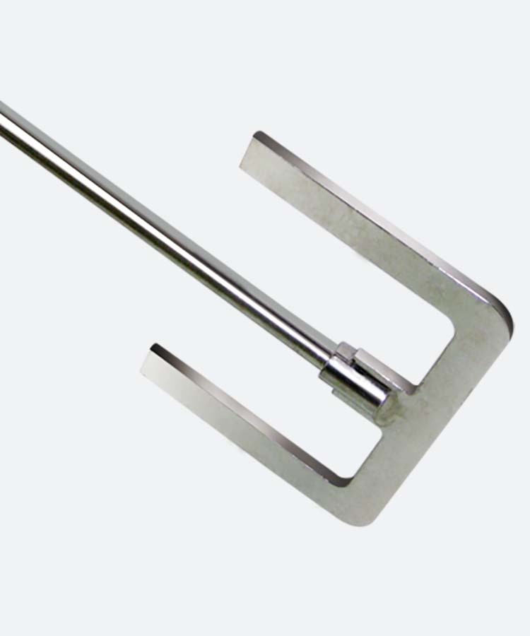
Low viscosity (typically below 100 mPa·s) is typically handled with marine or three-blade backward impellers, 2-4 baffles, impeller diameter about one-third of tank diameter, higher speed, and axial circulation lifting bottom particles. Medium viscosity (typically 100-1000 mPa·s) calls for larger-diameter turbine or gate impellers with lower speed and higher circulation flow. High viscosity (typically above 1000 mPa·s) requires the impeller itself to push material; ordinary axial impellers cannot establish circulation, so ribbon or anchor impellers or even a planetary mixer are used.
Off-bottom clearance is equally critical, generally 0.5-1 times impeller diameter. Too high and bottom particles are not lifted; too low and there is insufficient flow under the impeller, also leaving dead zones. With multiple impellers, the bottom one handles suspension and the upper one handles homogenization; spacing is generally 1-1.5 times impeller diameter. The table below gives typical experience ranges for common impellers:
| Impeller type | Applicable viscosity | Typical speed | Suspension feature |
|---|---|---|---|
| Marine propeller | <100 mPa·s | 150-300 r/min | Strong axial flow, high efficiency with baffles |
| Three-blade backward | <500 mPa·s | 100-200 r/min | Large circulation, medium-low viscosity |
| Turbine | 100-1000 mPa·s | 60-150 r/min | Shear plus circulation, medium viscosity |
| Anchor/gate | 1000-10000 mPa·s | 20-60 r/min | Impeller pushes material, scrapes wall |
| Ribbon/planetary | >10000 mPa·s | 10-40 r/min | Whole-body turnover for paste-like materials |
Should Baffles and the Tank Bottom Be Modified?
Bottom line: low-viscosity tanks almost always need baffles to prevent whole-body vortexing; a sloped or shallow-cone bottom visibly reduces dead zones.
Without baffles, low-viscosity liquid rotates as a whole, particles are thrown to the wall by centrifugal force and the bottom center becomes a dead zone. Adding 2-4 baffles of about one-tenth tank diameter in width converts tangential flow into axial flow, visibly improving suspension efficiency. High-viscosity slurries barely vortex, so baffles matter less and may be reduced or omitted.
Tank bottom geometry also affects suspension. Flat bottoms accumulate material at edges and center; shallow-cone or dished bottoms turn bottom liquid upward along the cone surface, noticeably reducing accumulation. For tanks with bottom discharge valves, the bottom slope is generally no less than 5 degrees to ensure clean discharge. When retrofitting an old tank, check the bottom type as well - otherwise even a larger motor may not solve the accumulation problem.
How to Judge Suspension in Production?
Bottom line: cross-check with bottom observation, sample comparison and current change; do not rely only on the tachometer.
The most direct method is a bottom sight glass: during normal suspension only fast-turning slurry is visible at the bottom, no static pile. For tanks without a sight glass, take samples from bottom and middle ports, weigh and compare solids content; deviation is generally kept within 10%. Running current also reflects state: a sudden current drop often means local settling has reduced impeller resistance; persistently high current may mean agglomeration or rising viscosity.
For acceptance, fix a reproducible procedure: same recipe, same charge, record performance around the critical suspension speed, then set the working speed. Then even if raw material density fluctuates slightly from batch to batch, there is a baseline to compare against instead of mistaking "this batch changed" for "equipment broke".
How Much Speed Margin Should Be Reserved?
Bottom line: the working speed is generally 1.2-1.3 times the critical suspension speed, and motor power should be checked for enough margin so that batch density fluctuations do not drop the tank out of suspension.
Critical suspension speed is calculated for the design material, but actual batches vary in solids content and particle size; a slightly larger density difference can cause re-settling. A 20%-30% speed margin is common industry practice - the cost is higher power consumption, the gain is stability. Beyond that, uniformity improves little, so speeds generally do not exceed 1.5 times the critical value.
Select the motor against the shaft power at working speed and consider the start-up condition. When starting, the impeller may be buried in settled solids, so start-up torque is notably higher than running torque; the motor and reducer should be checked against start-up duty, with motor power commonly taken at about 1.5 times running power. For variable-frequency drives, also check that the constant-torque speed range covers operation near the critical suspension speed.
How to Scale Up from Bench and Pilot Data?
Bottom line: scale-up from bench data to an industrial tank follows geometric similarity and dimensionless criteria; scaling speed proportionally to volume is either too conservative or too demanding on power - use dimensionless criteria as the bridge.
A 5-10 L lab tank may suspend well, but scaling to a 3 m³ industrial tank is not guaranteed. If volume grows by hundreds of times and speed is scaled by intuition, specific power rises sharply and the motor cannot cope; if speed is scaled conservatively, the bottom piles up again. The industry generally uses dimensionless criteria such as specific power per volume or Froude number for scale-up, deriving the industrial condition from bench data.
When requesting a proposal, pass the lab tank's impeller type, off-bottom clearance, baffle configuration and test speed to the equipment maker - far more useful than just describing "suspension is poor". The maker converts your bench condition into an industrial configuration and corrects it with operating data from similar tanks in its own production, which is more reliable than estimating from scratch. The main sources of scale-up deviation for suspension duty are tank bottom structure and the agitator seal, so settle both at the design stage together.
Further reading: - High-viscosity mixing equipment selection: from high-speed disperser to planetary mixer - How to arrange mixing tank nozzles: top connections and maintenance space design
This article is compiled by Hyline Shengda Equipment Manufacturing Co., Ltd. (hyline.cn). We specialize in stainless steel reactors, mixing tanks, storage tanks, dispersers, concentrators and complete chemical production line solutions, with non-standard custom design supported.
Q&A from this article
Frequently asked questions and answers from this article
Bottom line: the critical suspension speed (Njs) is the lowest speed at which all particle…
Related Products
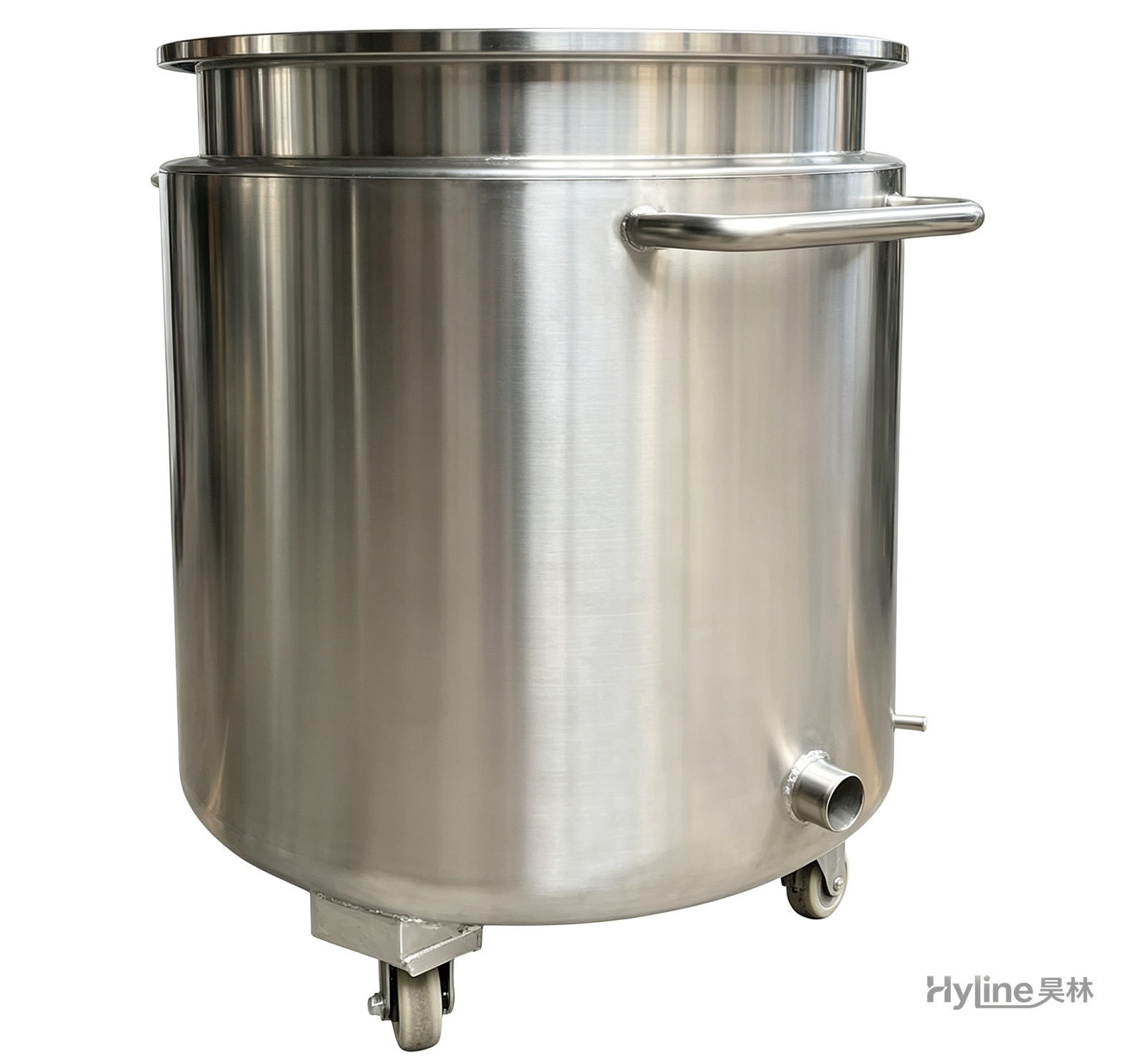
Stainless Steel Mixing Tank (Dispersion Drum)
Supporting vessel for dispersers and mixers in paints, coatings, adhesives, color slurries, inks and electronics. Available in 201/304 stainless with internal/external polishing and sloped bottom side discharge for complete draining.
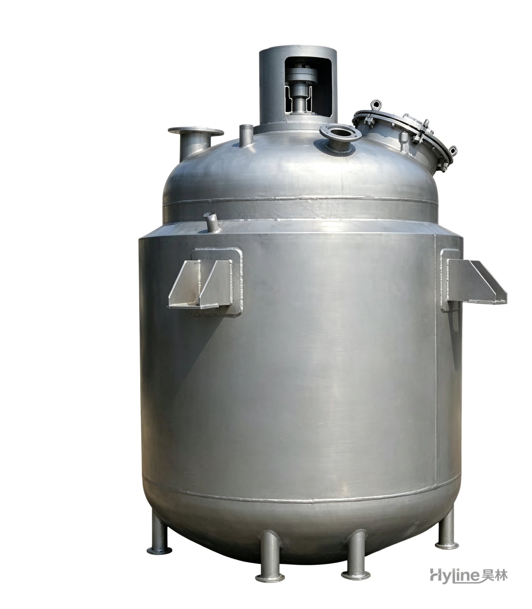
Jacketed Reactor
The typical main reaction vessel in chemical production. Mixing, heating and cooling disperse and mix materials for reaction and polymerization. The jacket circulates thermal oil/steam for heating or cooling water for temperature control.
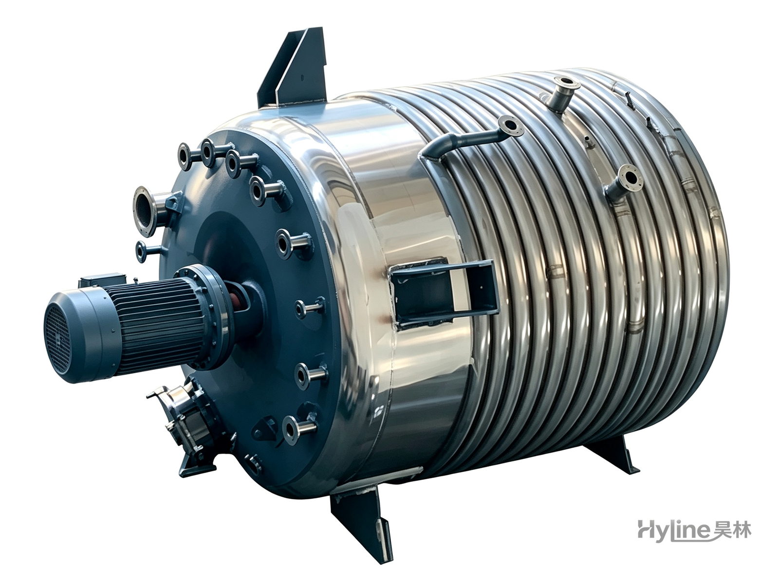
External Half-Coil Reactor
External half-pipe heating & cooling coils provide uniform, efficient heat exchange with zero material dead zones inside. Mirror-polished 304/316L stainless tank is clean and corrosion-resistant. For resin, new-energy slurry and pharmaceutical synthesis.
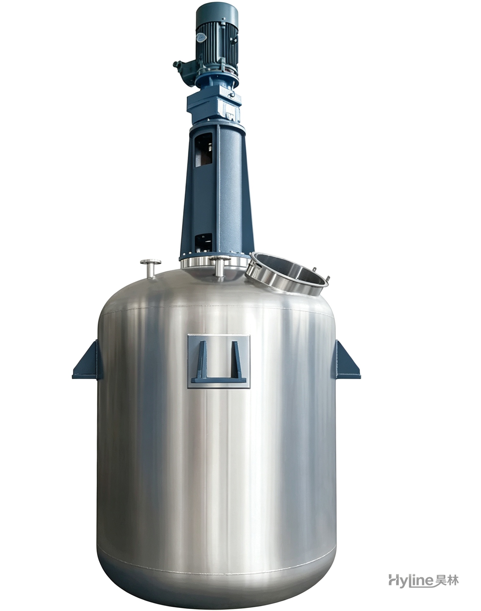
TC Series Mixing Kettle (Tinting)
For color matching in the paint industry and liquid-liquid / liquid-solid mixing in other industries. Uniform tinting, good miscibility, reasonable structure and powerful stirring.
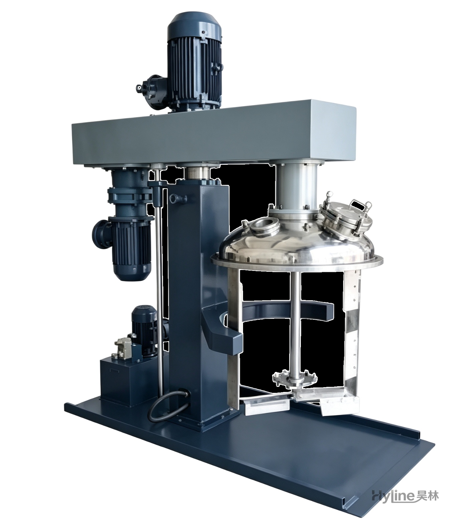
TSJ Series Concentric Twin-Shaft Mixer
Mixes materials of 3000-20000 cps. Low-speed blades with Teflon scrapers sweep the tank wall and push material to the center; high-speed toothed impellers disperse powerfully. High and low speeds run independently.
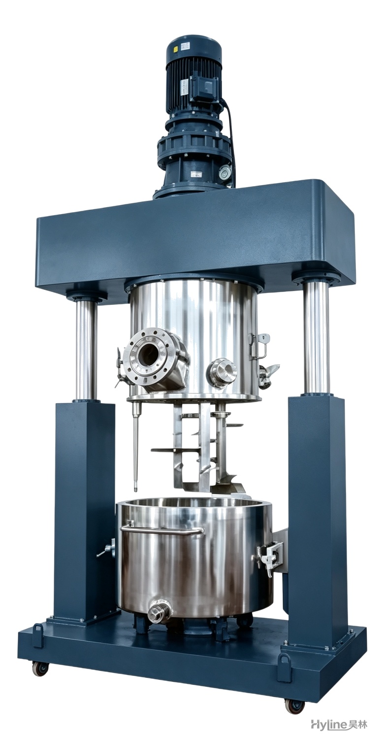
XJB Series Planetary Mixer
Planetary blades rotate and revolve simultaneously, creating complex material flow with no dead corners and easy discharge. Handles ultra-high-viscosity pastes of 10,000-8,000,000 cps for silicone, PU sealants, liquid silicone and electronic adhesives.