
How to choose a stainless steel reactor for the polyurethane prepolymer industry? Moisture-proof feeding, vacuum dehydration and temperature-controlled mixing essentials
11/13/2026
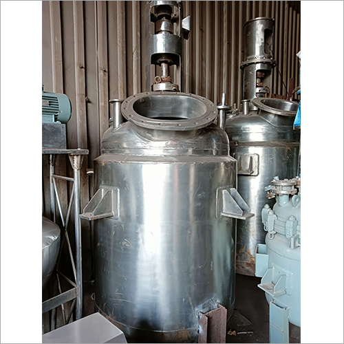
A polyurethane prepolymer is an intermediate made by pre-reacting polyisocyanates with polyols to consume most of the free monomer; downstream it becomes adhesives, coatings, elastomers and sealants. Workshops producing prepolymers fear three things most: water, concentrated heat release and viscosity that soon becomes unmixable. Equipment selection revolves around exactly these three: if water enters the system, isocyanate reacts immediately releasing carbon dioxide, the batch foams and is scrapped; the polymerization heat release is concentrated, and if temperature cannot be held down the batch gels; in the second half of the reaction viscosity climbs rapidly, and if mixing and heat transfer cannot keep up the whole kettle is wasted. From reaction requirements, material and inner surface, moisture-proof feeding, temperature control and mixing, to discharge and cleaning, this article sets out the selection logic for reactors in the polyurethane prepolymer industry so buyers can pin down the configuration.
What does the prepolymer reaction demand from the equipment?
One-sentence conclusion: a prepolymer reactor must satisfy moisture exclusion, temperature control and high-viscosity mixing at the same time — missing any one puts the whole batch at risk. Isocyanate meeting water produces carbon dioxide and urea, and bubbles left in the material are defects, so moisture must be excluded from raw materials, feeding and the vessel atmosphere alike; polymerization heat release is concentrated, so cooling capacity is sized for the peak, not the average load; in the later stage viscosity rises from hundreds to tens of thousands of millipascal-seconds or more, so impeller type and motor torque are chosen for the final viscosity, not the starting materials.
| Reaction stage | Material character | Equipment requirement |
|---|---|---|
| Feeding and dehydration | Polyol contains water to remove | Vacuum dehydration, dry nitrogen blanket |
| Dosing reaction | Concentrated exotherm, temperature sensitive | Adequate cooling and staged temperature control |
| Holding / curing | Viscosity keeps rising | High-torque mixing and good heat transfer |
| Discharge | High-viscosity liquid | Large-diameter outlet and heat-traced piping |
For buyers this table is the skeleton of the requirement list: match each configuration item to each stage when comparing quotations and nothing will be left out.
How to define material and inner surface?
One-sentence conclusion: 304 or 316L is the mainstream for prepolymer reactors, with fine-polished inner walls and dead zones under control — the core idea is dry, smooth, residue-free. Where the system is not chloride-sensitive and color requirements are moderate, 304 is sufficient; for light-colored or transparent products, or slightly acidic raw materials, 316L is the safer choice. The inner surface gets mechanical polishing with the grade set by product cleanliness requirements; welds are ground smooth inside and pickled-passivated so weld seams do not become the starting point of cured residue.
| Location | Recommended configuration | Rationale |
|---|---|---|
| Vessel material | 304 / 316L | Adequate corrosion resistance for neutral systems, set by cleanliness and medium |
| Inner surface | Mechanical polishing, grade per product requirement | Reduces clinging material and cured residue |
| Welds | Smooth internal grinding, pickling-passivation | Removes residue dead zones and corrosion sources |
| Agitator seal | Mechanical seal plus dry nitrogen blanket | Keeps moisture out of the vessel |
One reminder: for prepolymer systems the seal is not only about leak-tightness but about moisture. Water vapor creeping along the shaft seal also causes local foaming, so the mechanical seal flush and isolation plan should be designed around a dry nitrogen blanket — write this explicitly into the technical agreement.
Material certificates and acceptance documents are agreed at the procurement stage: material sheets, weld inspection records, polishing and passivation acceptance are delivered with the factory documents, and the pre-charging pressure test and leak check follow the reactor acceptance process. Once a prepolymer system is charged, the repair window is very narrow — control at the factory saves far more trouble than on-site remediation.
How to configure moisture-proof feeding and vacuum dehydration?
One-sentence conclusion: dehydrate the polyol under vacuum before feeding, keep a nitrogen blanket throughout feeding, and hold powder addition ports dry with a slight positive pressure. Polyols are strongly hygroscopic, and excess water directly hurts prepolymer quality; vacuum dehydration in the vessel or a dedicated drying tank before feeding is common practice, with vacuum level set by the drying requirement and the endpoint confirmed by moisture testing. Both pulling and breaking vacuum should use dry nitrogen or dry air — never let humid air straight into the vessel.
Powder filler and solid additive ports need the same moisture discipline: keep the hopper closed, purge with dry nitrogen before charging, and close it immediately after. Workshops that can do so feed powders through enclosed conveying, controlling both moisture and dust. The position and size of charging ports are laid out on the drawings according to the feeding method; retrofitting later both breaks the dry atmosphere and adds leak points.
The vacuum system itself also needs to match the dehydration duty: liquid-ring pumps are simple and tolerate vapor but have limited ultimate vacuum, and efficiency drops as the polyol approaches low moisture; dry vacuum pumps reach deeper vacuum and carry no water, suiting strict moisture targets. A buffer tank sits between vessel and pump; trace alcohols and light volatiles carried out during dehydration are condensed by a condenser before the pump, protecting it and cutting emissions. Valves on the line are zero-leakage types — air leaking into the negative-pressure section carries moisture too.
How to configure temperature control and mixing?
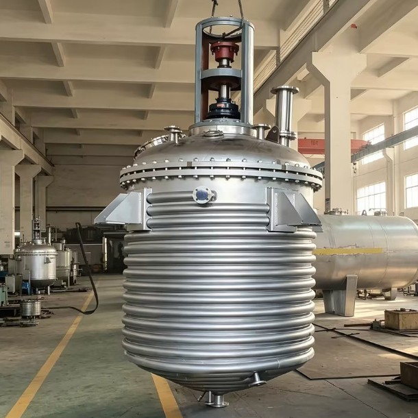
One-sentence conclusion: prefer evenly heating external coil or jacket structures, size cooling for the exotherm peak, and switch impeller stages as viscosity grows. Heating usually uses steam or thermal oil, switching to cooling water during the exothermic stage; the external half-coil structure of a half-coil reactor keeps the vessel interior free of coils, gives clean flow fields and easy wall cleaning, which is why it is a common choice for high-viscosity systems like prepolymers.
| Viscosity stage | Impeller suggestion | Supporting points |
|---|---|---|
| Low viscosity (dehydration, early dosing) | Paddle or propeller | Axial circulation and temperature uniformity |
| Medium viscosity (mid-late reaction) | Frame impeller | Covers the wall, prevents wall overheating and clinging |
| High viscosity (curing, before discharge) | Anchor plus helical ribbon | Wall-hugging heat transfer, removes temperature stratification |
Variable-frequency drive lets one mixer cover multiple viscosity stages: low speed during dosing to avoid gas entrainment, higher speed during curing to keep mixing. When final-stage viscosity is very high, in-vessel mixing mainly maintains temperature uniformity; if post-blending is even more viscous, the configuration logic of a planetary mixer — revolution plus rotation — moves high-viscosity material more effectively.
Heat transfer area is calculated from the exotherm curve: heat release concentrates during dosing, so the combined jacket-plus-external-coil surface must guarantee peak heat removal speed, not just average temperature difference. The in-vessel temperature sensor sits in the bulk liquid away from direct impeller disturbance, with jacket inlet and outlet points added; when the difference exceeds the set value, slow the dosing rate — better a longer batch than a temperature overshoot.
How to set batch scale and vessel capacity?
One-sentence conclusion: vessel volume is derived from batch size divided by the filling coefficient; for high-viscosity materials like prepolymers the coefficient is set conservatively, with headroom left for dosing and foaming. In a one-batch-per-kettle rhythm, too small a vessel fragments batches, while too large raises peak heat-removal pressure and mixing torque non-linearly along with cost. The common approach is to break the annual target into a batch plan, derive nominal volume from single-batch charge plus dosing headroom, then check workshop height, floor load and layout space. Multi-product workshops size the vessel for the main product and run minor products in the same kettle — one mixer covering several viscosity bands is exactly what variable-frequency drive is prepared for.
How to handle discharge and cleaning?
One-sentence conclusion: discharge the prepolymer within the viscosity window where it still flows, heat-trace the discharge line, and finish cleaning before residue cures. Size the bottom valve one step larger for flowability, keep the discharge line short and sloped toward the outlet, and add heat tracing when needed; for pumps, positive-displacement types are friendlier to shear-sensitive prepolymers.
Cleaning is the other maintenance priority. Once leftover material cures, it can only be scraped out mechanically, which damages the polished surface — the more it is scraped, the more it clings, a vicious cycle. The right way is solvent circulation cleaning before shutdown, running solvent through both lines and vessel while the material still flows. Solvent selection and recovery are arranged together per environmental requirements.
Cleaning acceptance is most directly checked by wipe tests: after draining the solvent, enter the vessel and wipe the inner wall, welds and impeller roots with white cloth — colorless and non-tacky means qualified. Adjust the solvent circulation time by residue condition, and open the line filters for inspection so residue does not wash into the next batch.
How to pin down the prepolymer reactor configuration?
One-sentence conclusion: give all four parameters — raw material system, target viscosity, batch size and cleanliness requirement — and the configuration will not drift. Material follows medium and cleanliness, heat transfer follows the exotherm curve, mixing follows final viscosity, discharge and cleaning follow process rhythm; with each line grounded, differences between quotations become readable and comparable.
Hyline Shengda Equipment Manufacturing Co., Ltd. (hyline.cn) has years of experience customizing reactors for high-viscosity polymerization systems such as polyurethane and adhesives: material and inner surface set by product requirements, exotherm cooling calculated from the process curve, mixing and discharge selected for final viscosity, and the moisture-proof feeding plan laid out on the drawings at once. Send us your polyol and isocyanate types, target viscosity and batch scale, and the prepolymer reactor proposal will be priced and sized together.
Further reading: - How to choose a stainless steel reactor for resin synthesis? Configuration essentials for esterification, polycondensation and polymerization - How to choose reactor impeller types? Propeller, anchor, frame and helical ribbon by material viscosity
This article is prepared by Hyline Shengda Equipment Manufacturing Co., Ltd. (hyline.cn)
Q&A from this article
Frequently asked questions and answers from this article
One-sentence conclusion: discharge the prepolymer within the viscosity window where it sti…
Related Products
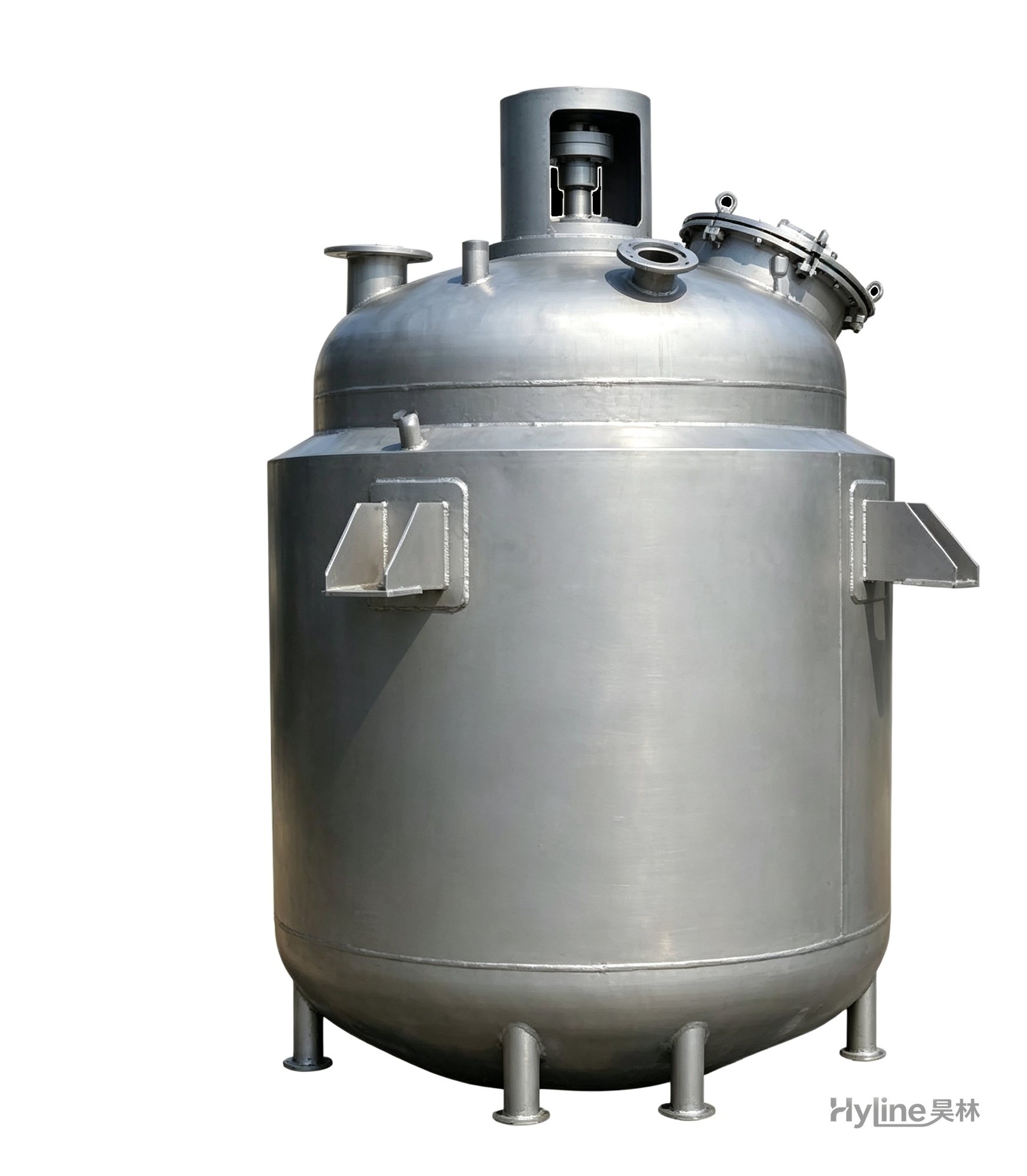
Jacketed Reactor
The typical main reaction vessel in chemical production. Mixing, heating and cooling disperse and mix materials for reaction and polymerization. The jacket circulates thermal oil/steam for heating or cooling water for temperature control.
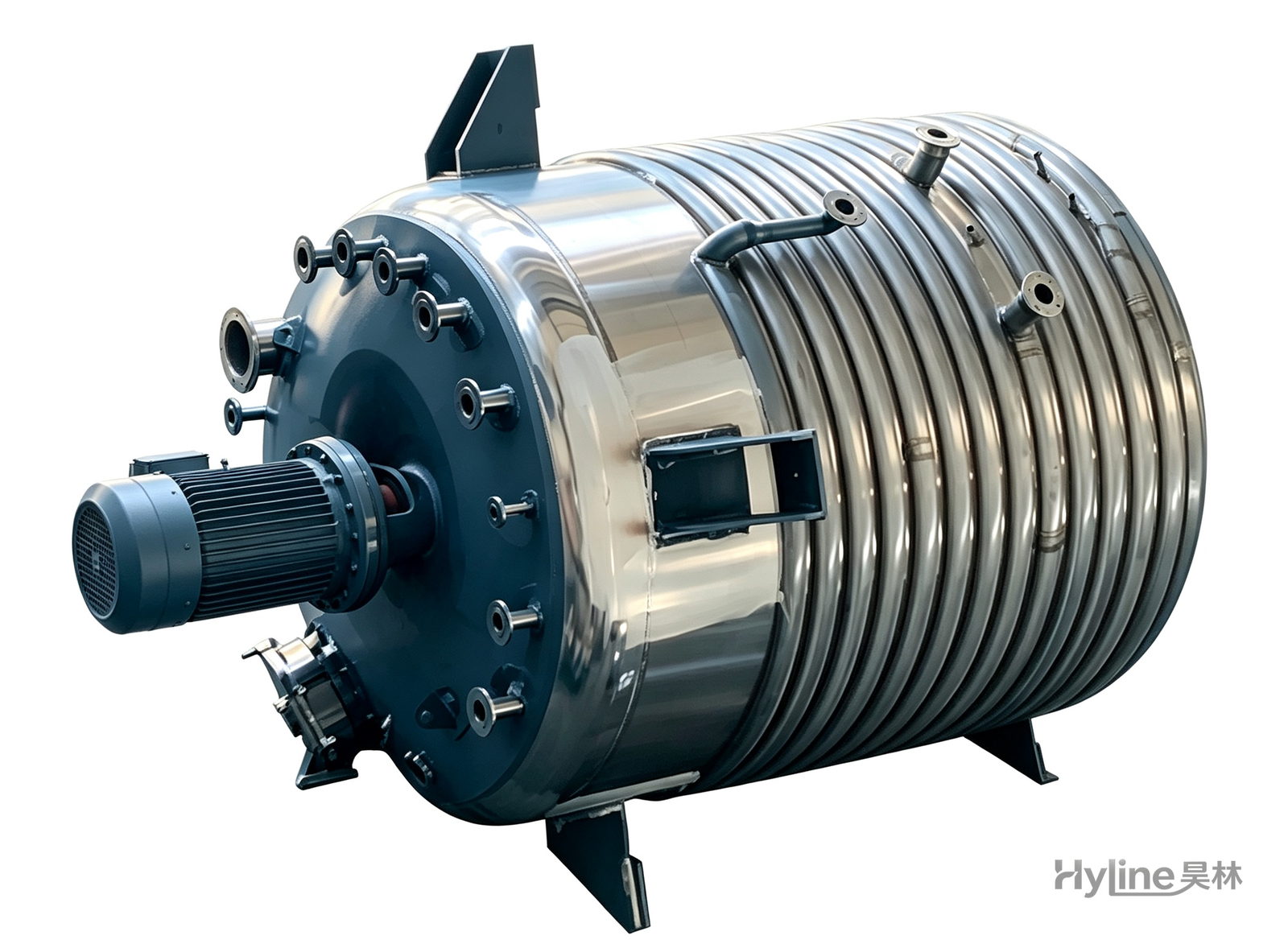
External Half-Coil Reactor
External half-pipe heating & cooling coils provide uniform, efficient heat exchange with zero material dead zones inside. Mirror-polished 304/316L stainless tank is clean and corrosion-resistant. For resin, new-energy slurry and pharmaceutical synthesis.
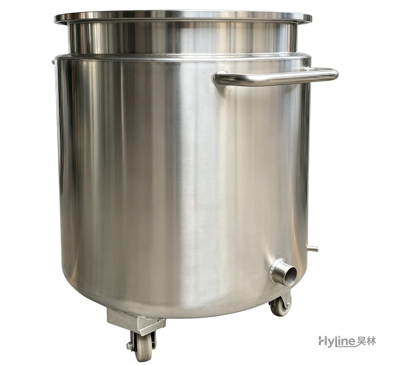
Stainless Steel Mixing Tank (Dispersion Drum)
Supporting vessel for dispersers and mixers in paints, coatings, adhesives, color slurries, inks and electronics. Available in 201/304 stainless with internal/external polishing and sloped bottom side discharge for complete draining.
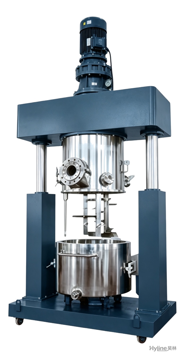
XJB Series Planetary Mixer
Planetary blades rotate and revolve simultaneously, creating complex material flow with no dead corners and easy discharge. Handles ultra-high-viscosity pastes of 10,000-8,000,000 cps for silicone, PU sealants, liquid silicone and electronic adhesives.