
How to Match Reactor Agitation Power, Motor and Gearbox? Estimate by Volume, Viscosity and Impeller Type
10/11/2026
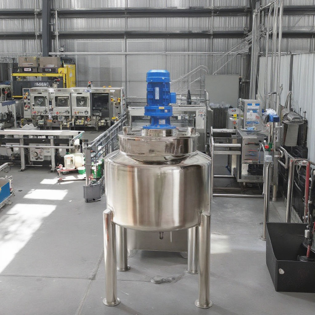
How to Match Reactor Agitation Power, Motor and Gearbox? Estimate by Volume, Viscosity and Impeller Type
The agitation system of a reactor determines mixing, heat transfer and reaction uniformity, and the power is the easiest part to get wrong. Too little power and the material will not mix properly, causing layering or uneven reaction; too much power and both the motor and the gearbox cost more, with higher running energy consumption. Conclusion first: estimate agitation power in four steps — volume, viscosity, impeller type and speed. Decide the impeller type and speed first, then calculate power from torque, and finally apply a safety factor of 1.2–1.5 to select the motor; the gearbox is matched by output speed and torque, not simply by power rating. This article explains the logic of each step and the common empirical values.
### Why cannot agitation power be judged by tank size alone?
Many people size the agitation power of a stainless steel reactor by volume: one kiloliter with 3 kW, two kiloliters with 5 kW. This works barely for low-viscosity, light mixing duty, but fails completely for high-viscosity materials — the same 2,000-liter tank may need ten times more power when filled with resin instead of water. The reason is that agitation power essentially overcomes the viscous resistance and inertia of the material: the more viscous the material, the larger the impeller, and the higher the speed, the higher the shaft power required. So the correct order is to define the process requirement first (impeller type, speed, mixing target), then derive the power; tank size is only one of the input parameters.
### How to decide the impeller type? It determines the power magnitude
The impeller type is the first decision of the agitation system because it directly sets the range of power demand. Industry experience is generally divided as follows: for low-viscosity mixing, heat transfer and homogenization, use propeller or turbine impellers, with low power demand per unit volume — "light mixing"; for medium-viscosity dissolving, dispersing and suspension, use paddle or frame impellers with medium power demand; for high-viscosity kneading, homogenizing and heat transfer, use anchor, ribbon or planetary mixer type large-torque low-speed impellers, where power demand per unit volume rises significantly. The judgment anchor is material viscosity: generally below 5,000 mPa·s use medium-low speed impellers, 5,000–50,000 mPa·s suggests ribbon or anchor plus paddle combinations, and above 50,000 mPa·s planetary or dual-shaft mixing should be considered. If the impeller type is wrong, no power calculation can save it.
### How do volume and batch size affect power?
Volume affects the "scale" of the agitation system. As a rule, agitation power is roughly proportional to the 5th power of impeller diameter and the 3rd power of speed, and impeller diameter roughly scales linearly with tank diameter, so power grows very fast when the tank is enlarged. For estimation, first set the batch size: batch loading is normally calculated at 60%–75% of tank volume, and liquid level determines impeller immersion depth and mixing effect; then determine impeller size from the ratio of tank diameter, liquid level and impeller diameter (generally impeller diameter is 1/3–1/2 of tank diameter), and enter power estimation. One rule is easy to miss: when the batch is too small, the impeller cannot be fully immersed and mixing efficiency drops sharply — no matter how much power is installed, the material will not mix evenly. So the process usually recommends a batch of no less than 50% of tank capacity, and power is sized by the design batch, not by an empty or half-filled tank.
### How to decide speed and tip speed?
Speed is decided by two logics: for low-viscosity processes that need fast mixing, decide speed by impeller tip speed; for high-viscosity processes that need uniform heat transfer, decide speed by allowable shear and torque. Common empirical values: turbine impeller tip speed 2–5 m/s, propeller 5–10 m/s, anchor and ribbon 0.5–2 m/s. Once the tip speed is set, speed equals tip speed divided by circumference (π × impeller diameter), directly calculable. For emulsifying and dispersing processes, speed should be raised with high-shear structures; for heat-sensitive or shear-sensitive materials, speed must be limited to avoid local overheating or emulsion breaking. After speed is set, the gearbox reduction ratio follows: the motor synchronous speed is generally 1,450 rpm (4-pole motor), divided by the required agitation speed, which gives the approximate reduction ratio range.
### How to estimate agitation power? Are there empirical values?
Accurate agitation power calculation requires fluid mechanics formulas; on-site selection more often uses empirical estimation. For low-viscosity materials with conventional impellers, start with "power per unit volume": light mixing generally 0.3–0.8 kW/m³, medium mixing 0.8–2 kW/m³, high-viscosity strong mixing 2–5 kW/m³; then divide by motor efficiency (generally 0.85–0.9) and transmission efficiency (gearbox plus seal, generally 0.85–0.95) to derive the motor rating. For example, a 5 m³ reactor for medium-viscosity resin at 1.5 kW/m³ gives about 7.5 kW shaft power; divided by 0.85 efficiency, the motor needs about 8.8 kW, rounded up to the standard 11 kW, then with a safety factor of about 1.2, 15 kW is a safe configuration. This estimation suits preliminary selection; the final design should be verified by the equipment manufacturer with software based on material parameters.
| Agitation duty | Typical impeller | Power per unit volume | Applicable viscosity | Typical speed |
|---|---|---|---|---|
| Light mixing | Propeller / turbine | 0.3–0.8 kW/m³ | Low viscosity | 100–300 rpm |
| Medium mixing / dissolving | Paddle / frame | 0.8–2 kW/m³ | Medium viscosity | 60–150 rpm |
| Strong mixing / high-viscosity heat transfer | Anchor / ribbon | 2–5 kW/m³ | High viscosity | 20–80 rpm |
| Planetary / dual-shaft | Planetary / dual-shaft | Calculated by material | Very high viscosity | 10–60 rpm |
### How to select the gearbox? Torque matters more than power
The core parameters of a gearbox are output torque and output speed, not power. The same 11 kW motor with a 1:5 versus a 1:40 gearbox differs eight times in output torque and serves completely different purposes. The general steps: first set the required output speed (derived from tip speed), then calculate shaft torque (torque ≈ power × 9550 ÷ speed), and select a gearbox model that can sustain this torque and run stably at the target speed for long periods. For gearbox types, cycloidal or helical gearboxes are common for small and medium power; hard-toothed-face gearboxes or structures with planetary reduction stages are used for large-torque high-viscosity duty; installation is by site space — horizontal, vertical or flange-mounted. One reminder: a bigger reduction ratio is not always better; when speed is too low, heat transfer of high-viscosity materials slows down and batch time extends, so balance it with the process rhythm.
### What else matters in motor selection? Explosion-proof and protection rating
Beyond power, motor selection also depends on two site parameters: explosion-proof rating and protection rating. Chemical workshops generally set the motor explosion-proof rating by the hazardous area classification; common requirements are ExdⅡBT4 or ExdⅡCT4, determined by media category and area grade; protection rating is generally IP55 or above, raised in dusty and humid environments to prevent dust and moisture ingress. For high-viscosity duty, pay attention to starting characteristics: the start needs to overcome the static resistance of the material, so a variable-frequency motor or a motor with higher starting torque is preferred; adding a VFD also enables soft start and speed regulation, friendlier for process commissioning. A common misconception: explosion-proof does not mean "any one will do" — the same rating still differs in temperature class and mounting style, so verify the nameplate covers the on-site media.
### How do the shaft and seal follow the power?
After power, motor and gearbox are settled, the transmission chain end — the shaft and the seal — must be checked together. The shaft is generally sized by torque and overhung length; a shaft that is too thin will twist and the impeller will wobble; for long overhung lengths or high-viscosity duty, add an intermediate bearing or a bottom stabilizer. Seals are selected by media sealing requirements: organic solvents and low-viscosity liquids generally use single mechanical seals; materials with solids or easy crystallization use double mechanical seals with flushing liquid; food and pharmaceutical clean duty use aseptic seals by hygienic standards; packing seals are simple and low cost, suitable for low speed and low sealing requirements, but leakage is relatively larger. The shaft, seal and power configuration are one integrated system — include all three in the technical agreement when purchasing so the manufacturer designs them as a whole, which is more reliable than assembling parts separately.
### Should a VFD and interlock be included?
The electrical supporting of an agitation system commonly includes a VFD plus interlock control. The main value of a VFD is adjustable speed: during commissioning different speeds can be tried to find the best condition, during production speed can be adjusted by material viscosity, and soft start reduces shock to the gearbox and large motor. For interlocks, it is generally recommended to interlock the agitator motor with temperature and level: in exothermic reactors, reduce speed or stop automatically when temperature exceeds the limit; prohibit starting agitation at low level to prevent dry running from damaging the seal and bearings. A practical experience: when VFD and explosion-proof requirements appear together, either place the VFD outside the hazardous area or select an explosion-proof VFD; the protection rating and temperature rise of the electrical cabinet must also be considered, otherwise on-site acceptance can be held up at the electrical stage.
### What to watch when scaling up to production?
When scaling from pilot to production, power does not scale proportionally — this is the most common pitfall of agitation systems. A 100-liter pilot tank with 0.75 kW scaled to 5 m³ is not 0.75 × 50 = 37.5 kW; since agitation power grows with the 5th power of impeller diameter, direct multiplication by volume either overestimates or underestimates badly, depending on whether the impeller type changes. Generally maintain similarity of key parameters when scaling: keep power per unit volume similar for low-viscosity mixing, keep impeller tip speed and torque density similar for high-viscosity mixing, and check that the impeller-to-tank diameter ratio stays in a reasonable range. Scale-up design should be provided by the equipment manufacturer based on agitation software simulation; scaling by experience alone on site easily leads to uneven mixing or motor overload.
### Summary
Reactor agitation power configuration is essentially "process first, mechanics second": decide impeller type, speed and batch size first, estimate power by viscosity, then select the gearbox, motor, shaft and seal, and finally add VFD and interlocks. Empirical values such as power per unit volume, tip speed and safety factor suit preliminary selection; the final design should be calculated by material parameters. When purchasing a reactor, put material viscosity, target speed, batch size, explosion-proof requirements and clean grade into the technical agreement so the manufacturer configures the agitation system as a whole — far easier than replacing the motor or gearbox after delivery. Below are real photos of a reactor workshop and agitation drive; the on-site arrangement of motor, gearbox and shaft can be referenced.

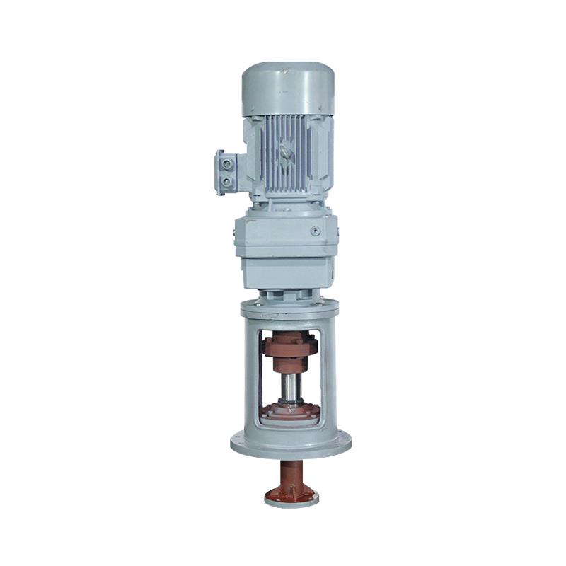
Further reading: - How to maintain a reactor agitation system: shaft, seal and impeller assembly points - Selection of high-viscosity mixing equipment: from high-speed dispersers to planetary mixers
This article is compiled by Shenzhen Hyline Equipment Manufacturing Co., Ltd. (hyline.cn); all information rights belong to the original authors. Main products: stainless steel reactors, mixing tanks, storage tanks, dispersers, concentration tanks and complete chemical process lines; custom (non-standard) manufacturing supported.
Q&A from this article
Frequently asked questions and answers from this article
Speed is decided by two logics: for low-viscosity processes that need fast mixing, decide …
Related Products
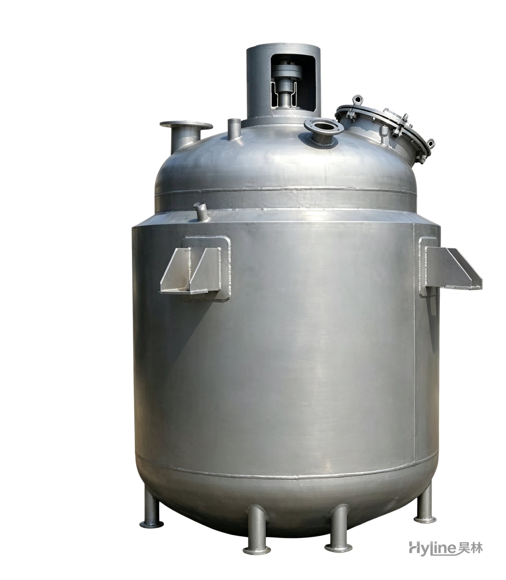
Jacketed Reactor
The typical main reaction vessel in chemical production. Mixing, heating and cooling disperse and mix materials for reaction and polymerization. The jacket circulates thermal oil/steam for heating or cooling water for temperature control.
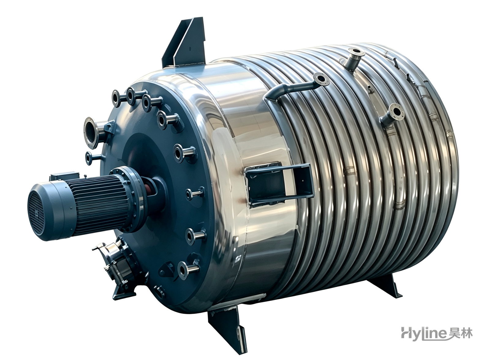
External Half-Coil Reactor
External half-pipe heating & cooling coils provide uniform, efficient heat exchange with zero material dead zones inside. Mirror-polished 304/316L stainless tank is clean and corrosion-resistant. For resin, new-energy slurry and pharmaceutical synthesis.
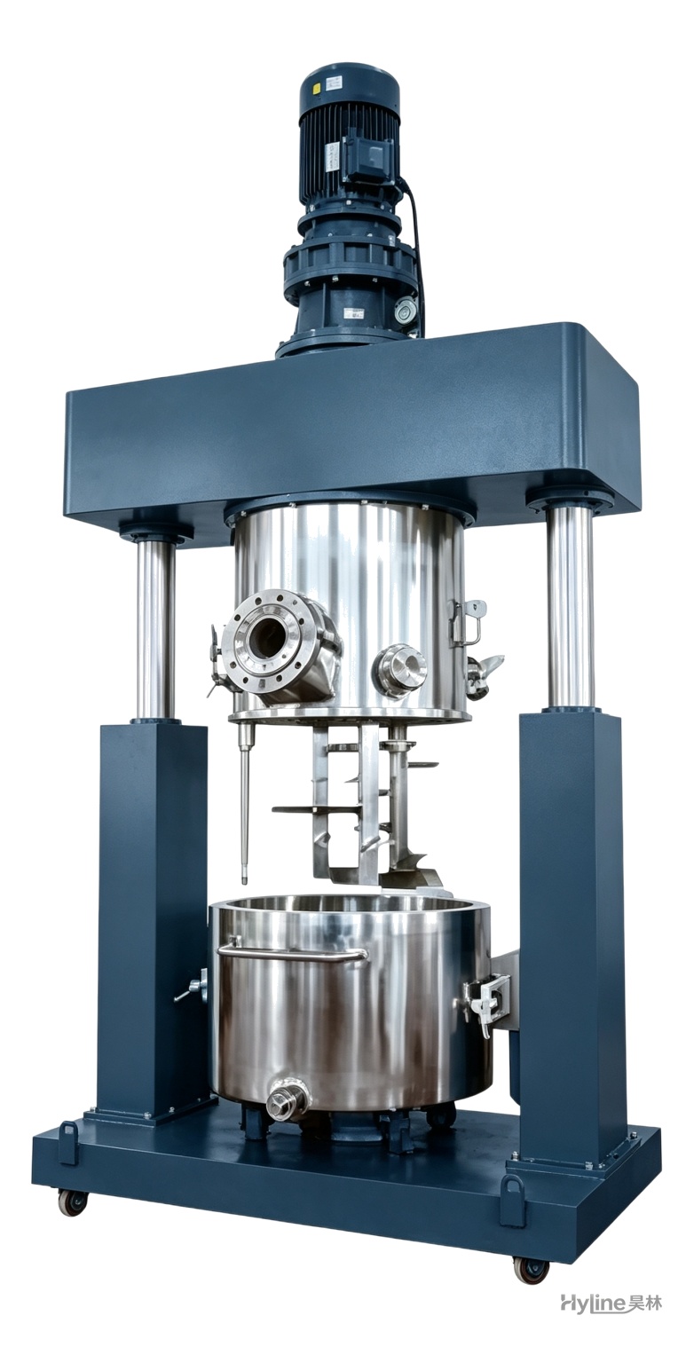
XJB Series Planetary Mixer
Planetary blades rotate and revolve simultaneously, creating complex material flow with no dead corners and easy discharge. Handles ultra-high-viscosity pastes of 10,000-8,000,000 cps for silicone, PU sealants, liquid silicone and electronic adhesives.
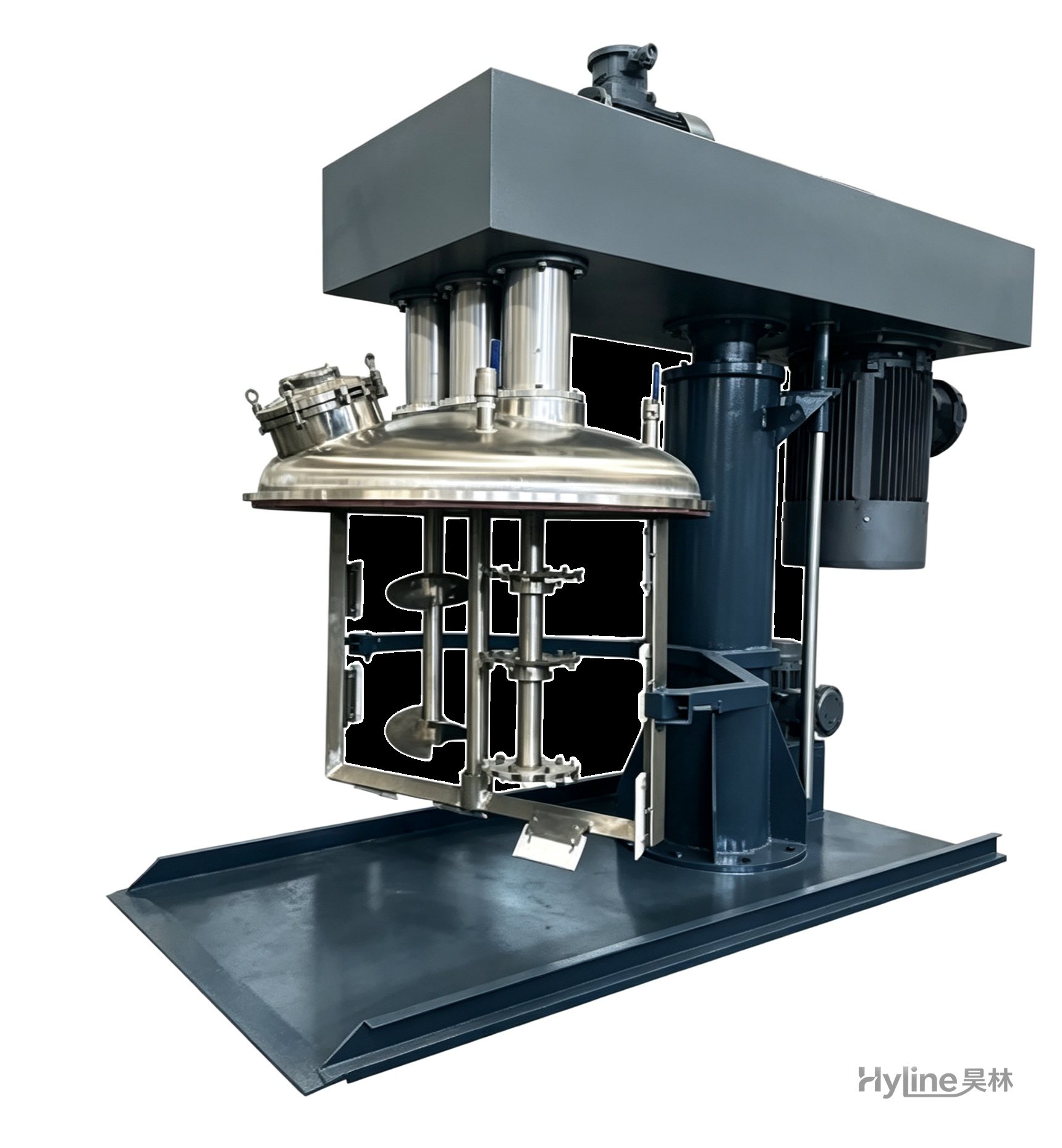
SJ Series Multi-Function Mixer
A new high-efficiency mixer for high-viscosity materials, rapidly dispersing, dissolving and homogenizing. Widely used in offset printing inks, putties and adhesives. Vacuum type customizable.
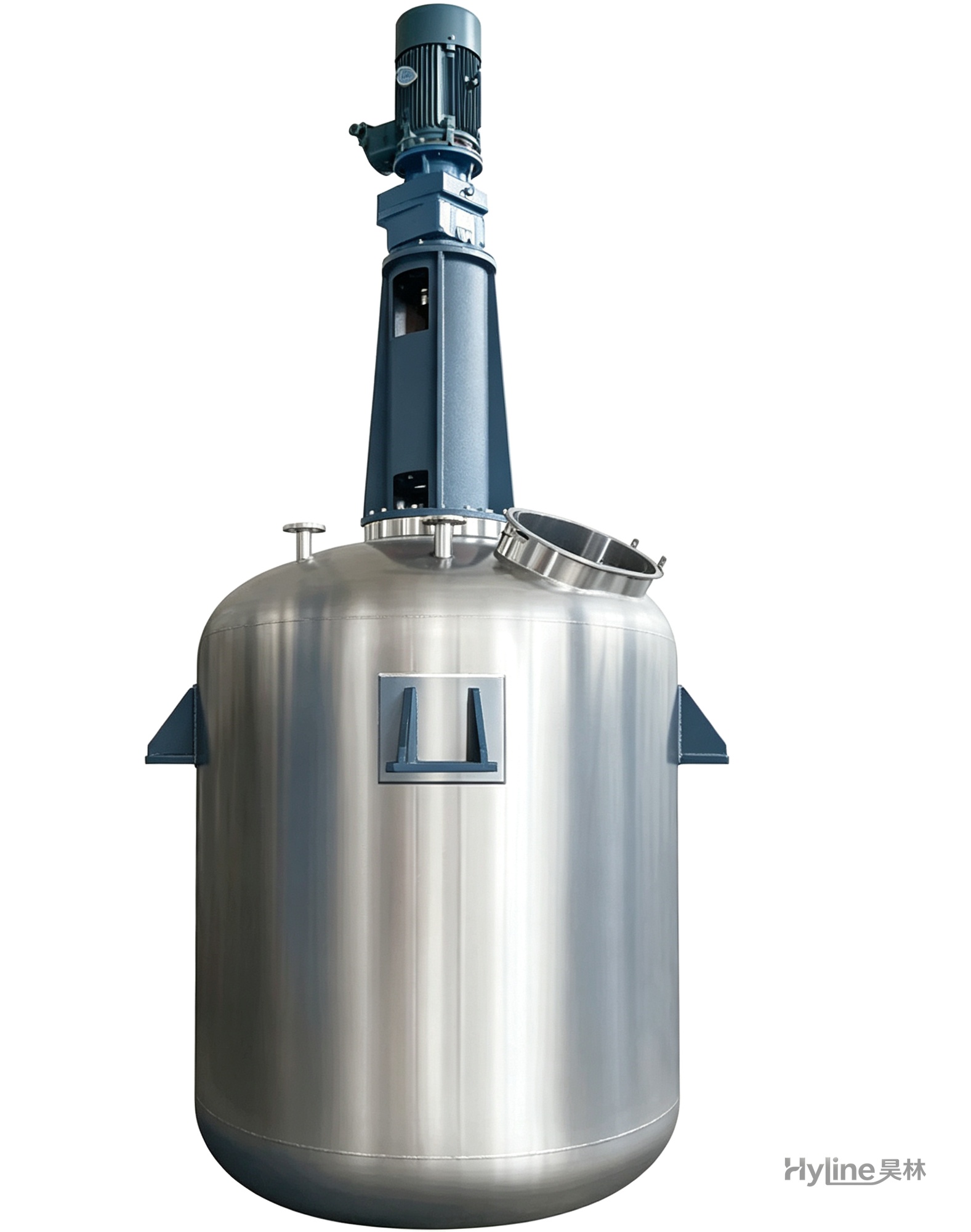
TC Series Mixing Kettle (Tinting)
For color matching in the paint industry and liquid-liquid / liquid-solid mixing in other industries. Uniform tinting, good miscibility, reasonable structure and powerful stirring.
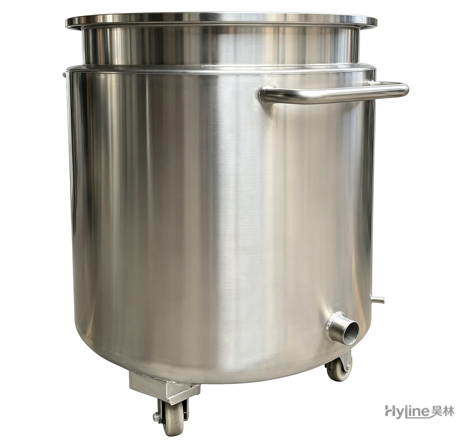
Stainless Steel Mixing Tank (Dispersion Drum)
Supporting vessel for dispersers and mixers in paints, coatings, adhesives, color slurries, inks and electronics. Available in 201/304 stainless with internal/external polishing and sloped bottom side discharge for complete draining.