
How to configure reactor cleaning? CIP spray balls, high-pressure washing and dead-zone design
11/11/2026
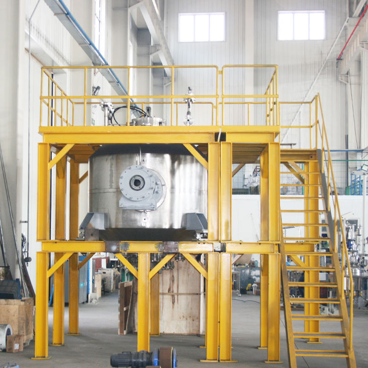
Buyers and process engineers running multi-product workshops that make resins, coating film-formers and fine chemical intermediates share one recurring discovery: after the reactor arrives, cleaning consumes more labor and time than the reaction itself. Each batch runs a different formula, and if residue from the last batch is not removed properly, the next batch suffers from off-color and contamination at best, or a full kettle of rejected material at worst. A cleaning solution is not just a spray ball bolted to the lid — spray method, dead-zone treatment, cleaning media and acceptance criteria all have to be settled at the equipment selection stage. Our reactors can be configured with CIP-in-place and manual cleaning access to match the material behavior, and this article walks through the key points so you can get the configuration right before ordering.
When is CIP required, and when is manual cleaning the better deal?
Short answer: choose CIP first when batches follow one another quickly, materials cure easily, or hygiene standards are strict; choose manual cleaning when the schedule is relaxed and residues rinse off easily.
The core value of CIP (clean-in-place) is that the vessel stays closed — no lid opening, no vessel entry, no guesswork. Spray balls wash the walls, impeller and internals in a closed loop. A 2000 L reactor can be cleaned in 40 to 60 minutes on a programmed cycle, while opening the manway and hosing it down by hand usually takes two to three hours. For a workshop that switches formulas two or three times a day, that gap directly determines output. Water, caustic solution and rinse water switch in a preset sequence with controlled temperature and flow, so cleaning quality stays consistent across shifts instead of depending on whoever happens to be on duty.
CIP is not universal, though. If the material does not stick to the wall, batches are a full day apart, and the vessel is under 500 L, manual cleaning is cheaper and often more thorough — an operator can enter the vessel (after draining, gas-freeing, with a standby person outside) and treat residue exactly where it sits, wiping the spots a spray ball cannot reach. For pasty or crosslinking materials, the impact of spray water cannot break up cured lumps; these duty cycles need manual re-cleaning and high-pressure access whether or not CIP is fitted. List your materials' curing tendency and changeover rhythm before deciding whether CIP is the main cleaning route or an auxiliary one — this order should never be reversed.
Take the cleaning media seriously as well. Hard rinse water leaves a calcium-magnesium scale film on the wall that is easy to confuse with residue film at acceptance, so use softened water for the final rinse in multi-product workshops; after caustic and acid washes, displacement rinsing must be thorough — residual cleaner can contaminate the next batch. Cleaning effluent counts as process wastewater: decide where it is collected and how it is treated at the plant-layout stage, not after the equipment has arrived.
How to choose the spray device: fixed ball, rotating ball or 360° rotary head?
Short answer: fixed spray balls for water-soluble low-viscosity residues, rotating spray balls for wall-fouling and light scaling, and 360° rotary cleaning heads with circulating cleaning solution for high-viscosity, high-solids duty.
A fixed spray ball has no moving parts and works purely on coverage and impact of the water flow. It is simple and nearly maintenance-free, and it handles residues that are still wet; its weakness is uneven coverage — on larger diameters the flow reaching the far wall weakens noticeably. A rotating spray ball spins on the reaction of the jet itself, concentrating the flow into a scanning band that sweeps the wall ring by ring; the impact is much stronger, and it clearly outperforms the fixed ball on fouled walls. High-solids media can jam its bearing, so confirm self-filtering or an upstream filter. A 360° rotary cleaning head uses finer nozzles at lower speed, laying cleaning solution over every corner as a misting fan; it is the mainstay for viscous, high-solids, scaling-prone duty, but it needs a cleaning-solution circulation loop with heating, which raises both investment and maintenance.
| Spray method | Coverage | Suitable media | Requirements |
|---|---|---|---|
| Fixed spray ball | Full-circle, weak impact | Low-viscosity water-soluble residue | Ordinary cleaning water |
| Rotating spray ball | Scanning, strong impact | Fouling, light scaling | 3-6 bar, upstream filtration |
| 360° rotary head | Mist coverage of dead zones | Viscous, high-solids, scaling | Solution circulation + heating + filtration |
Positioning matters as much as type: below 1.5 m diameter, one ball at the top center is enough; on larger vessels, or vessels with baffles or internal coils, the flow gets blocked by internals and two balls placed diagonally should be considered. Leave margin in the throw distance from ball to farthest wall and verify coverage at the actual spray pressure — the same ball can have a very different effective radius at 3 bar versus 6 bar.
Design a dedicated CIP loop instead of borrowing process piping. Cleaning solution leaves the vessel bottom, passes through a pump and filter, and returns to the spray ball; keep the piping sloped with drain valves at the low points — the small volume of liquid left in the piping will otherwise be flushed straight back into the vessel on the next cycle. Select the pump head for spray pressure plus line losses; a process circulation pump pressed into cleaning duty rarely matches either flow or pressure, so coverage tested through it means nothing.
Where do the dead zones hide? These spots are the usual suspects
Short answer: the backs of impeller blades, baffle gaps, the root of thermowell sleeves, the inside of the manway neck and the seal area are the five classic dead zones — plan flow paths for cleaning water at the selection stage.
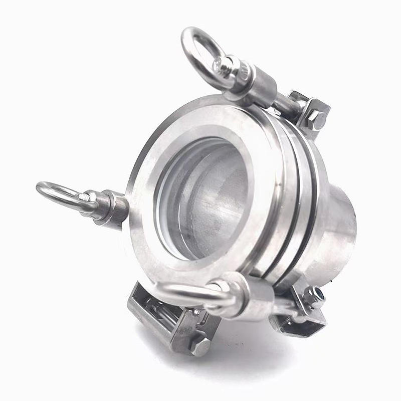
For anchor, gate and helical impellers that run close to the wall, the backs of the blades and behind the support arms are typical collection points; so are the crevice between baffle and wall and the edge where a gasket protrudes past the shell. The remedy is structural, not extra washing afterwards: widen the impeller-to-wall gap, make baffles removable or gap them off the wall for rinse flow, keep thermowells short with a smooth root transition. The inside lip of the manway neck and the grooves of a quick-open clamp are missed by manual wiping and underserved by spray flow alike, so put them on the mandatory inspection list.
Internal coils affect cleaning even more directly. A half-coil reactor keeps the heat-transfer surface outside the shell, leaving the vessel interior completely open: spray coverage is good and manual wiping is unobstructed, a structural advantage for multi-product workshops with strict cleaning demands. Internal coils transfer heat efficiently, but the space between coil layers is a natural blind zone for the flow — when fitting CIP, check inter-layer coverage explicitly and add auxiliary nozzles if needed, so the heat-transfer gain is not eaten up by cleaning problems.
When to bring in high-pressure washing and chemical cleaning?
Short answer: for aged scale that rinsing cannot shift, move to high-pressure water first and chemical cleaning second — do not start with solvent soaking.
High-pressure washing with a 20 to 60 bar manual lance or automated cleaning arm has a clear peeling effect on dried, hardened resin and polymer deposits, and it introduces no chemical-residue risk, which makes it the standard weapon against stubborn fouling in multi-product workshops; the cost is heavy labor and the need for ventilation and visibility in a closed vessel. Chemical cleaning is the second step: 2-3% hot caustic circulated at 60-70°C for one to two hours handles oils and most organic residues efficiently; for carbonized layers and inorganic scale that resist alkali, move on to acid or a formulated cleaner matched to the medium. Before using any cleaner, run a compatibility test on a small area to confirm it will not harm the polished surface or the welds, and keep the test record. In a closed vessel, cleaner vapors accumulate, so the procedure must include thorough fresh-water displacement and gas-freeing — never skip this safety step.
Wastewater and solids handling also needs to be arranged in advance. Caustic and acid effluents are process wastewater — confirm collection piping and neutralization before ordering; scraped scale is solid waste to be disposed of by category. None of these items appear on the equipment quotation, but the cleaning line will not run without them — list them in the configuration so everything is ready at commissioning.
How to accept the cleaning result?
Short answer: three gates — visual inspection, wipe tests and the next batch — with acceptance criteria written into the purchase contract at the trial-production stage.
The most intuitive acceptance is visual inspection with a water-film check: no visible residue film on walls, impeller or internals, and rinse water forming a continuous film without beading or breaking, which basically confirms cleanliness. For stricter duty, use the white-cloth wipe test around the blade backs and baffle crevices — no visible stain on the cloth means pass. The final gate is the color and contamination check on the first kettle of the next batch — the strictness of the cleaning standard is ultimately judged by product quality, and a standard set too loosely will cost a batch of material far more than what was saved on cleaning hardware. Acceptance documentation should include the CIP piping diagram, spray ball model and coverage test records, so future product changes and formula revisions have something to fall back on.
How to finalize the cleaning configuration?
Cleaning configuration balances material, structure and cleaning media, and the parameters interlock: impeller clearance shapes cleaning access, spray pressure sets the coverage radius, and the type of internals determines the number of dead zones. Hyline Shengda Equipment Manufacturing Co., Ltd. (hyline.cn) has extensive experience configuring reactors and charge tanks for multi-product duty: spray method chosen by curing tendency, dead zones pre-controlled through internals layout, CIP and manual access matched to the changeover rhythm. Send us your material viscosity, curing tendency and batches per day, and we will work out the cleaning scheme together with the configuration and quotation.
Further reading: - How to accept a reactor before delivery? No-load, load testing and leak checks - How are pickling, passivation and electropolishing done on stainless equipment?
This article is prepared by Hyline Shengda Equipment Manufacturing Co., Ltd. (hyline.cn)
Q&A from this article
Frequently asked questions and answers from this article
Short answer: three gates — visual inspection, wipe tests and the next batch — with accept…
Related Products
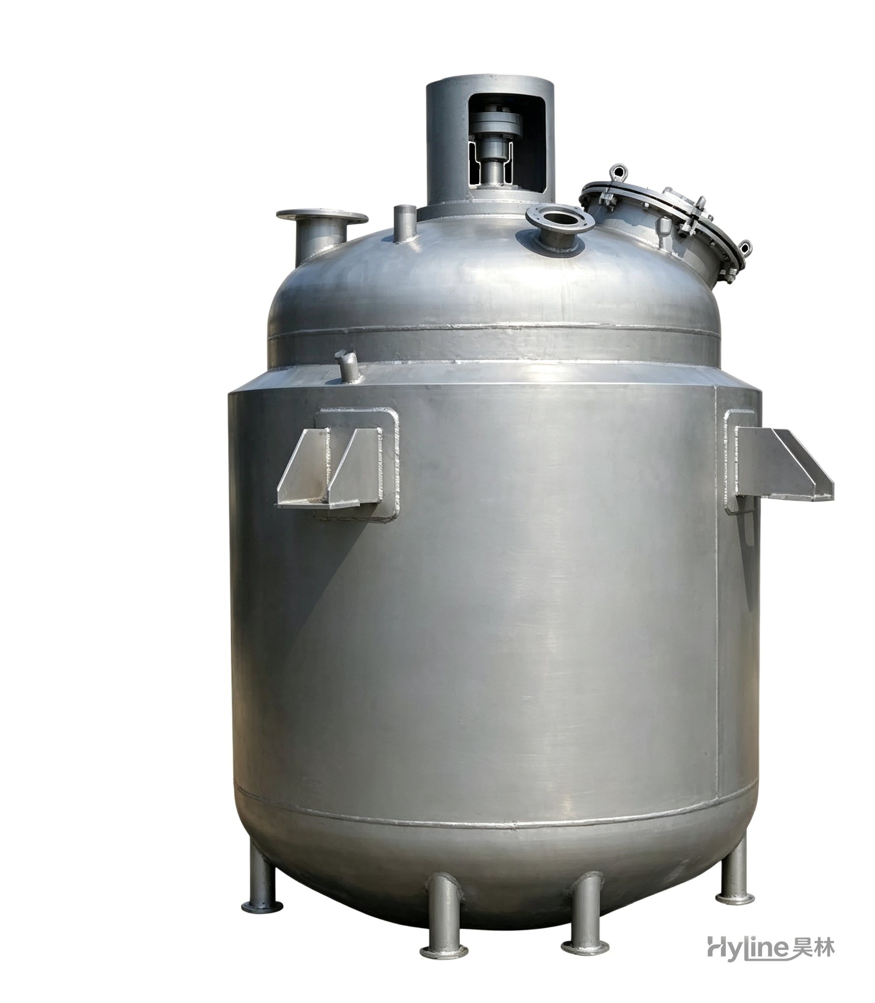
Jacketed Reactor
The typical main reaction vessel in chemical production. Mixing, heating and cooling disperse and mix materials for reaction and polymerization. The jacket circulates thermal oil/steam for heating or cooling water for temperature control.
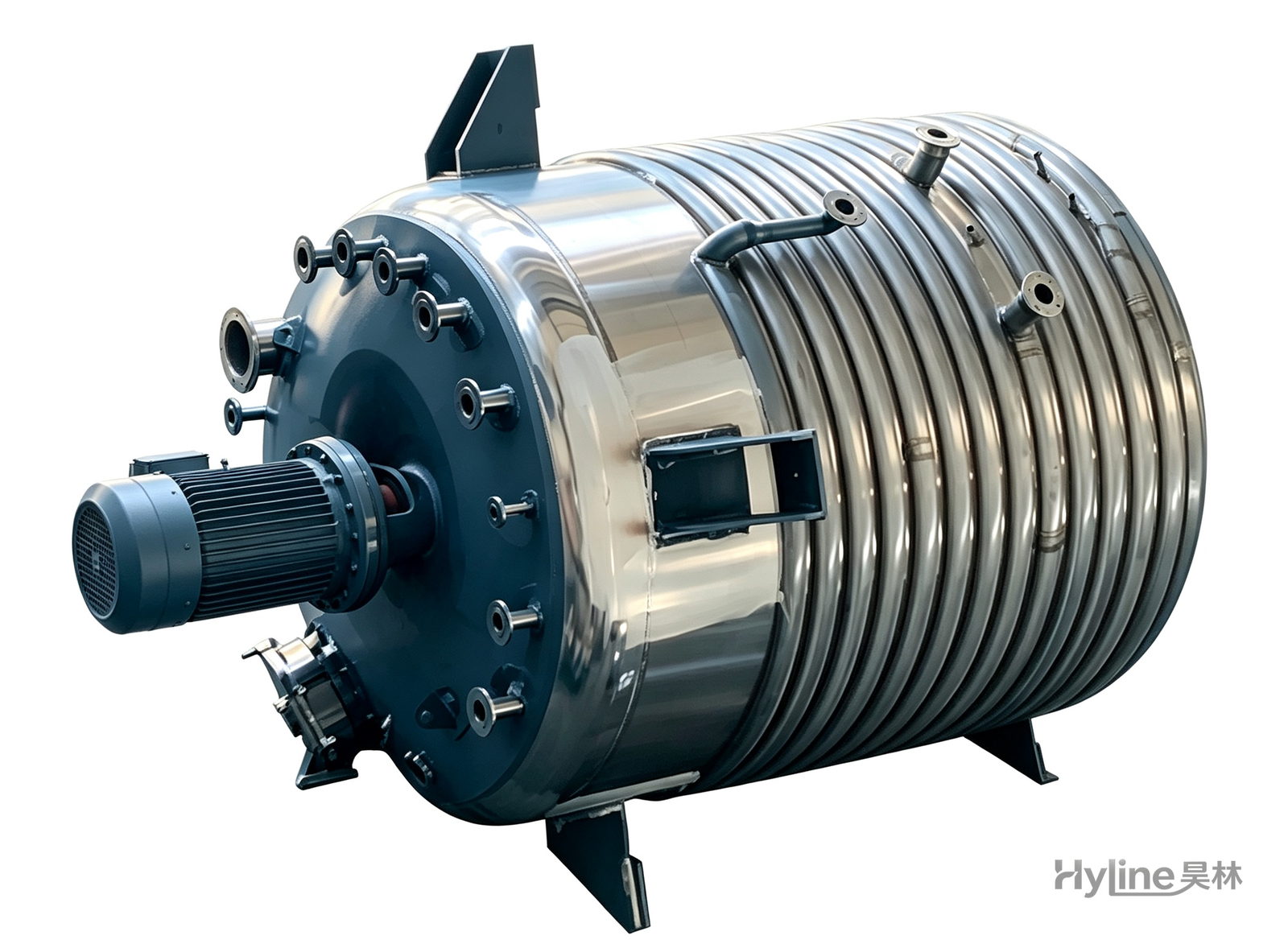
External Half-Coil Reactor
External half-pipe heating & cooling coils provide uniform, efficient heat exchange with zero material dead zones inside. Mirror-polished 304/316L stainless tank is clean and corrosion-resistant. For resin, new-energy slurry and pharmaceutical synthesis.
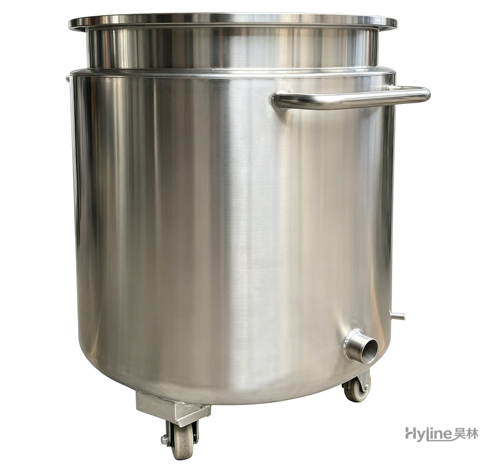
Stainless Steel Mixing Tank (Dispersion Drum)
Supporting vessel for dispersers and mixers in paints, coatings, adhesives, color slurries, inks and electronics. Available in 201/304 stainless with internal/external polishing and sloped bottom side discharge for complete draining.
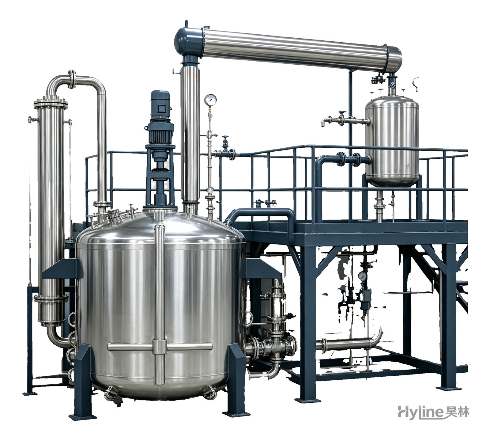
Complete Resin Production Equipment
Resin production packages built around the reactor, with vertical fractionating column, horizontal condenser and water separator for full synthesis, dehydration and reflux processes. Sizes from 300L to 30000L.