
How to Configure Explosion-Proof Protection for Stainless Steel Reactors? Explosion-Proof Motors, Electrical Control and Static Grounding Essentials
10/28/2026
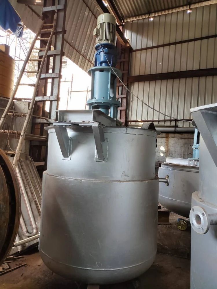
Why Must Reactors in Solvent Workshops Be Configured as Explosion-Proof?
Bottom line: stirring, charging and venting of a reactor all release flammable vapor; once motor sparks or static discharge meet it, an explosion follows. Reactors in solvent-borne coating, resin and adhesive workshops must be configured as a complete explosion-proof package.
An explosion needs three conditions at once: flammable vapor, an oxidizer and an ignition source. Solvent-borne coatings, resins and adhesives commonly use ethyl acetate, toluene, xylene and ketones, which have low flash points and high volatility. Stirring, material movement, charging and venting push the vapor concentration inside and around the reactor into the explosive range. The common ignition sources are motor commutation sparks, discharge inside terminal boxes, static on the agitator shaft and human-body static. Explosion-proof configuration is therefore not just installing an explosion-proof motor; it is a complete package covering the motor, electrical equipment, static grounding and inerting/venting, and missing any one link can cause an accident.
How Are Hazardous Areas and Explosion-Proof Ratings Determined?
Bottom line: first divide the workshop into Zone 0, 1 and 2 by the probability of vapor presence, then select equipment by gas group and temperature class. Coating and resin workshops generally start at IIB T4.
Area classification follows the probability of vapor presence: continuous or long-term presence is Zone 0, likely during normal operation is Zone 1, and occasional short-term presence is Zone 2. Areas around manholes, vents and sampling ports of reactors are usually treated as Zone 1 or Zone 2, depending on the process and safety assessment. Equipment selection then depends on two items: gas group and temperature class. Common solvents such as toluene, xylene and ethyl acetate mostly fall into gas group IIA or IIB, and most solvents have auto-ignition temperatures above 200℃, which places them in class T3 or T4. In practice, reactor motors in coating and resin workshops are generally selected as Ex d IIB T4: flameproof, gas group IIB, maximum surface temperature not exceeding 135℃, which covers most common solvent conditions.
| Hazardous area | Vapor presence | Common equipment type |
|---|---|---|
| Zone 0 | Continuous or long-term | Intrinsic safety Ex ia, special type |
| Zone 1 | Likely in normal operation | Flameproof Ex d, increased safety Ex e |
| Zone 2 | Occasional and short-term | Non-sparking Ex n, intrinsic safety |
How Are Explosion-Proof Motors and Gearboxes Configured?
Bottom line: the motor is selected as flameproof or increased-safety type, and the terminal box, cable entry and gearbox are all part of the explosion-proof package. IIB T4 usually covers most solvent conditions.
The motor body, terminal box and fan cover must all carry the corresponding explosion-proof type. Cables enter through explosion-proof flexible conduits or glands, and the terminal cavity must be properly sealed. When variable-speed control is needed, the inverter is generally placed in the electrical room or a flameproof cabinet, and the motor end uses an explosion-proof inverter-duty motor. Gearboxes themselves do not generate sparks, but couplings, guards and mounting bolts must be tightened to explosion-proof practice, and the flameproof faces must not be damaged during maintenance. If a half-coil reactor is heated by thermal oil or hot water, the heating system must be checked for explosion-proof requirements as well; neither electrical nor heat sources may be left as a blind spot. The explosion-proof motor must also match the power and speed required by the agitation: stirring power is generally estimated by volume and medium viscosity, and the power density of typical coating and resin stirring is roughly 0.3 to 1 kW per cubic meter, depending on the impeller type and speed. For an explosion-proof inverter-duty motor, check the constant-torque capability in the low-speed range to avoid insufficient starting torque. The rated motor speed and the gearbox ratio together bring the impeller tip speed into the range required by the process, so the explosion-proof package satisfies both safety and process requirements.
How Are Electrical Control and Instrumentation Made Explosion-Proof?
Bottom line: keep control cabinets outside the hazardous area, leave only intrinsically safe instruments and explosion-proof operating devices inside, and design signal loops as intrinsically safe. This is both cheaper and safer.
PLCs, inverter cabinets and power cabinets are concentrated in the electrical room or a control room outside the hazardous area; the fewer devices inside the area, the safer. Instruments that need local display in the hazardous area should be intrinsically safe type (Ex ia), with signal loops passing through safety barriers into the control cabinet. Local operating columns, push buttons and indicator lamps are selected as flameproof type. Temperature, pressure and level transmitters are likewise selected as intrinsically safe or flameproof, with conduit runs and proper isolation between zones. Electrical work inside hazardous areas must be performed by certified personnel per the drawings, and every loop is verified after wiring.
How Is Static Grounding Done?
Bottom line: the vessel, agitator shaft, piping and flanges are bonded section by section into the anti-static grounding net; static grounding resistance is generally controlled within 100Ω, and grounding is done before charging and sampling.
The reactor body has a dedicated grounding connection, and the agitator shaft normally leads static into the vessel through a conductive slip ring or carbon brush. Inlet and outlet piping is bonded across each flange, hoses are anti-static hoses with a conductive spiral wire, and the whole system is tied into the workshop anti-static grounding net. Static grounding resistance is generally accepted at no more than 100Ω; this is a separate requirement from the 4Ω protective grounding and cannot replace it. For low-conductivity pure solvents and resin systems, the charging flow rate must be controlled: in general, the initial velocity inside the vessel should not exceed 1 m/s and may be raised gradually after the liquid level rises, to reduce static accumulation. Operators wear anti-static clothing and conductive shoes, and touch a grounding device to discharge body static before sampling.
How Are Nitrogen Blanketing and Venting Configured?
Bottom line: nitrogen blanketing brings the gas-phase oxygen content down, a flame arrester is installed on the vent, and the two together control the explosion conditions. The oxygen content is generally kept below 8%.
Nitrogen blanketing pulls the vessel gas phase from flammable back to inert: continuous nitrogen supply at a slight positive pressure keeps oxygen below the lower explosive limit, generally controlled below 8%, with the exact value determined by solvent type and safety assessment. A breather valve or relief device maintains the slight positive pressure and prevents the vessel from collapsing under vacuum; a flame arrester on the vent outlet stops external flame from flashing back. A common interlock is to automatically boost nitrogen and alarm when oxygen content or pressure is abnormal. For reactors with intermittent charging and frequent lid opening, blanketing also reduces air ingress and works together with vent purging.
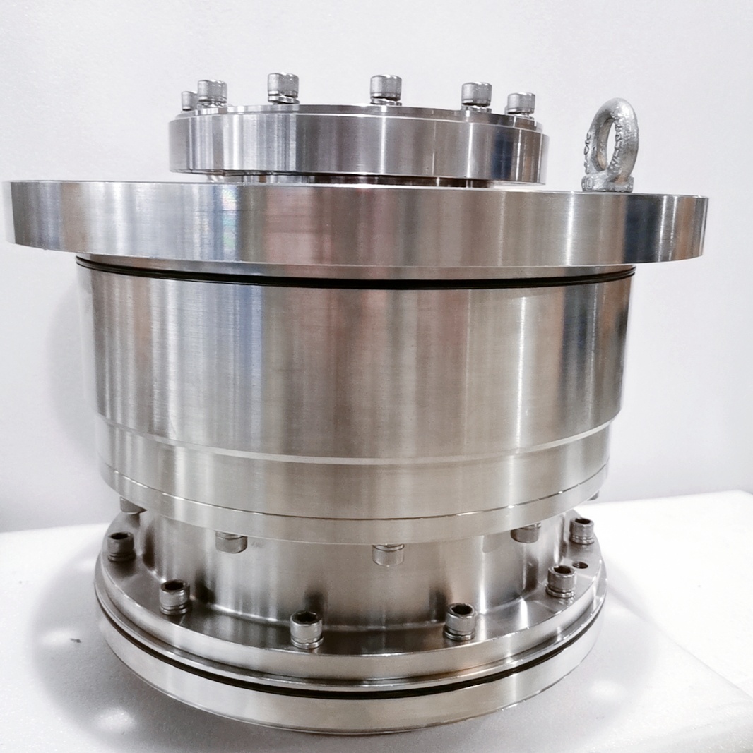
What Are the Seal and Safety-Accessory Requirements for Explosion-Proof Reactors?
Bottom line: flammable media call for a double mechanical seal with flushing, and the manhole, sight glass and safety valve are configured by pressure rating. Seal failure is the main entry point for explosion accidents.
The agitator shaft penetration is the weakest leakage point. For flammable solvents, a double mechanical seal is generally preferred, with seal oil or nitrogen pressurizing and flushing the seal chamber so the medium cannot escape; small reactors where a mechanical seal is not feasible may use a magnetic drive to eliminate the dynamic seal entirely. Manhole gaskets, sight-glass glass and flange gaskets are selected by medium corrosivity and pressure rating, and glass sight glasses are of explosion-proof type. The safety valve, rupture disc and nitrogen blanketing are interlocked: relieve overpressure first, then alarm. After maintenance, reassembly must follow the procedures for flameproof-face cleanliness, bolt torque and gasket replacement.
What Are the Common Misunderstandings in Explosion-Proof Configuration?
Bottom line: replacing only the motor, doing only grounding, or placing the explosion-proof cabinet inside the workshop are all misunderstandings. Explosion protection is a whole of equipment, electrical design and operation.
Misunderstanding one: only the motor is replaced, while the terminal box and cable entry remain ordinary parts, so sparks still come out of the terminal cavity. Misunderstanding two: grounding is done, but static removal from the agitator shaft is ignored, so the charge on the shaft and impeller cannot enter the grounding net. Misunderstanding three: the explosion-proof control cabinet is placed at the edge of the hazardous area, blurring the area boundary and underestimating the risk. At acceptance, check the equipment rating device by device against the area drawing, and measure the grounding resistance point by point against the grounding drawing, so that these misunderstandings are kept out before commissioning.
How Are Acceptance and Routine Inspection Arranged?
Bottom line: verify the explosion-proof nameplate and certificates at acceptance; check grounding and seals every shift; measure grounding resistance quarterly; and record the explosion-proof status in the equipment ledger.
On arrival of a new reactor, first check the explosion-proof marking, gas group and temperature class on the nameplate against the site media, and verify the explosion-proof certificates and wiring records for the electrical part. Every shift, check motor temperature rise, running sound, seal leakage and any looseness of bonding jumpers; every quarter, measure and record the static grounding resistance with an earth tester. Before hot work, replacement and purging must pass first; after disassembly, flameproof faces must not be ground or painted, and no bolt may be missing. Include the explosion-proof checks in the equipment ledger, keep every test and repair on file, and within two years a complete explosion-proof status record is formed.
Explosion-proof configuration is a system: from area classification, motor selection, electrical control and instrumentation to static grounding, any weak link disables the whole protection. When a project raises explosion-proof requirements, first obtain the area drawing and medium parameters, then check item by item in the order of this article, and finally close the loop with acceptance data.
Summary
Reactor explosion-proof configuration can be split into four tasks: classify the area first, then select equipment by rating, and use static grounding plus nitrogen blanketing and venting as the double safeguard. During selection, obtain the solvent's gas group and temperature class first, then decide the motor rating, instrument type and grounding scheme, so that the purchased equipment matches the actual condition. Our stainless steel reactors support non-standard customization with explosion-proof motors, explosion-proof electrical control and nitrogen-blanketing interfaces; selection for solvent-borne coating and resin workshops is welcome for discussion.
Related reading: - How to configure explosion-proof protection for a disperser? - How to configure pressure rating and safety accessories for a reactor?
This article is compiled by Hyline Stenda Equipment Manufacturing Co., Ltd. (hyline.cn), mainly supplying stainless steel reactors, mixing tanks, storage tanks, dispersers, concentrators and complete chemical line supporting equipment, with non-standard customization supported.
Q&A from this article
Frequently asked questions and answers from this article
Bottom line: the vessel, agitator shaft, piping and flanges are bonded section by section …
Related Products
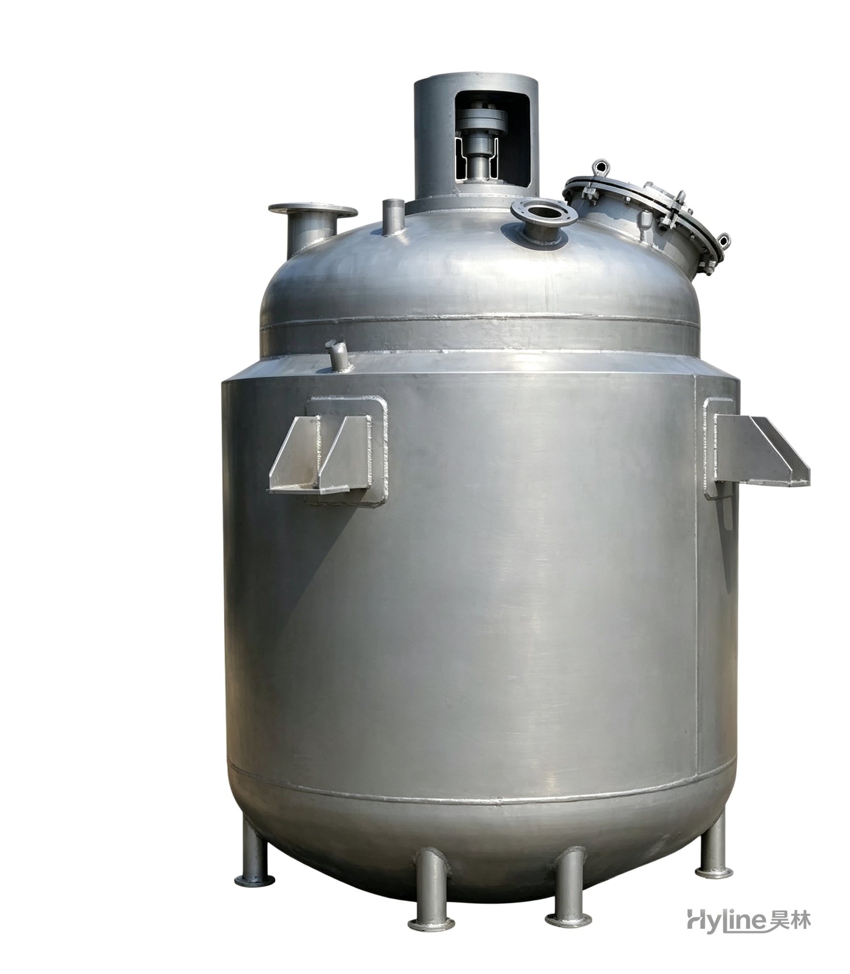
Jacketed Reactor
The typical main reaction vessel in chemical production. Mixing, heating and cooling disperse and mix materials for reaction and polymerization. The jacket circulates thermal oil/steam for heating or cooling water for temperature control.
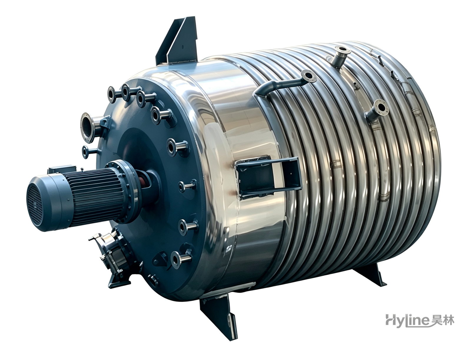
External Half-Coil Reactor
External half-pipe heating & cooling coils provide uniform, efficient heat exchange with zero material dead zones inside. Mirror-polished 304/316L stainless tank is clean and corrosion-resistant. For resin, new-energy slurry and pharmaceutical synthesis.
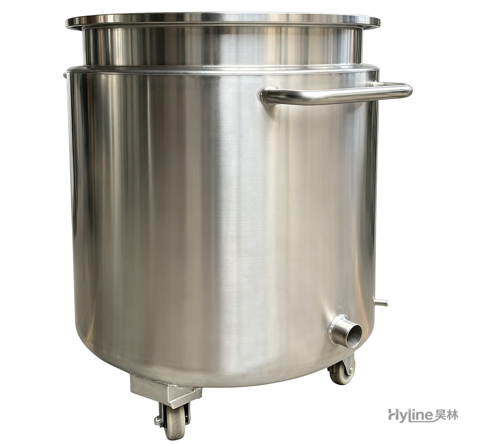
Stainless Steel Mixing Tank (Dispersion Drum)
Supporting vessel for dispersers and mixers in paints, coatings, adhesives, color slurries, inks and electronics. Available in 201/304 stainless with internal/external polishing and sloped bottom side discharge for complete draining.
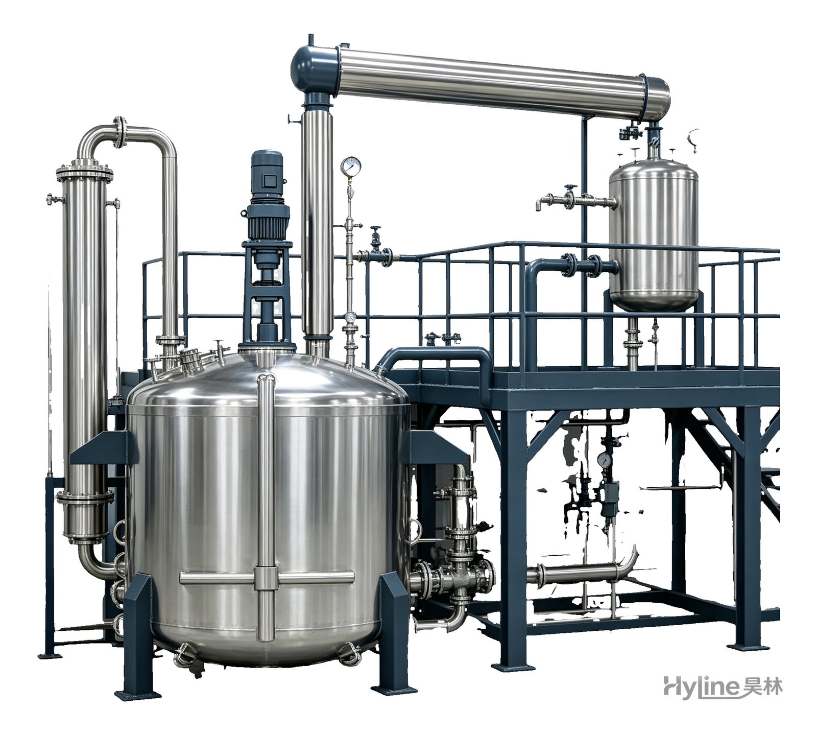
Complete Resin Production Equipment
Resin production packages built around the reactor, with vertical fractionating column, horizontal condenser and water separator for full synthesis, dehydration and reflux processes. Sizes from 300L to 30000L.