
How to configure an inlet distributor for stainless steel storage tanks? Anti-impact, anti-foaming and uniform feeding essentials
10/24/2026
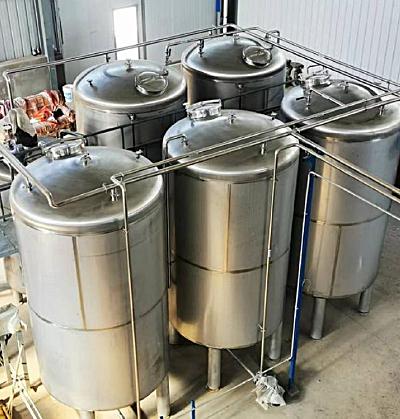
When a stainless steel storage tank is being fed, the liquid stream rushing straight to the tank bottom, large amounts of foam and uneven stratification of the material inside are three common problems in tank service. If the inlet nozzle is arranged casually without a distributor, the high-speed stream falls from the tank top, impacts the bottom and welds, and foam churns on the liquid surface; in mild cases metering and pumping are affected, and in severe cases easy-foaming media overflow the tank opening and the electrostatic risk rises. Many people think feeding is only a matter of one pipe, but in fact the configuration of the inlet nozzle and distributor directly determines the mixing uniformity, foam level and service life of the tank. This article explains what an inlet distributor does, what types are available and how to determine the selection parameters, helping you configure the feed system by medium and tank type.
Why add a distributor to the storage tank inlet?
One-sentence conclusion: the distributor splits a concentrated high-speed stream into multiple low-speed uniform streams, reducing impact, suppressing foam and improving stratification; it is a standard configuration of tank feed systems.
When the feed pipe goes directly into the tank, the stream impacts the bottom and the opposite wall at a high velocity, creating a high risk of local wear and fatigue at the impact point, and the tumbling stream also entrains air into the liquid to form foam. After a distributor is installed, the single stream is split into multiple small streams flowing out evenly in several directions, the impact energy is dispersed and the liquid-surface disturbance is reduced. According to common industry experience, the feed velocity is generally controlled within 0.5~1.5m/s (converted by pipe diameter and flow), and the opening velocity of the distributor is even lower, so the liquid enters the tank with near-zero impact. For easy-foaming media, solid-containing liquids and high-level tanks, the benefit of a distributor is the most obvious.
What problems does feed impact cause?
One-sentence conclusion: feed impact causes fatigue of the bottom welds, foam and air entrainment, electrostatic accumulation and liquid stratification; these problems only show up after accumulation over time.
The problems caused by impact fall into four categories: first, the tank bottom and welds — a high-speed stream continuously scours the same position, and the welds and bottom plate become locally thinner; according to common industry experience, the thinning rate of the plate in the impact zone can be obviously faster than in normal areas. Second, foam and air entrainment — the tumbling stream pulls air into the liquid, the foam layer squeezes the effective volume, and pumping is prone to cavitation. Third, static electricity — low-conductivity organic solvents accumulate static charges during impact and splashing, and foam and mist droplets are high-risk forms of electrostatic discharge. Fourth, stratification — single-point feeding makes it hard for media of different densities to mix evenly, and the representativeness of sampling and metering drops. All four categories are alleviated by feed distribution and velocity control.
What types of distributors are available?
One-sentence conclusion: common distributors fall into four types — perforated pipe, baffle, bell-mouth and tangential feeding — selected by the foaming tendency and impact sensitivity of the medium.
| Type | Structure | Suitable conditions | Features |
|---|---|---|---|
| Perforated pipe | small holes evenly arranged on a horizontal pipe | ordinary liquids, solid-containing liquids | simple structure, fairly even velocity distribution, most common |
| Baffle | deflecting plate below the inlet | high impact, deep tanks | disperses impact energy, slightly more complex to make |
| Bell-mouth | pipe end expanded into a bell | low-viscosity clean media | simple and low-resistance, suppresses jetting |
| Tangential feeding | introduced tangentially along the wall | conditions needing rotating distribution | guides swirl, used with mixing |
The perforated-pipe distributor is the most common in storage tanks and dosing tanks of the chemical, food and coating industries. The total number and diameter of openings are matched to the feed flow and tank diameter; generally the opening velocity is controlled within 0.3~1.0m/s, and the holes are evenly spaced to ensure the stream is evenly distributed over the tank cross-section.
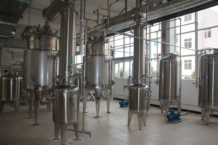
How to select a distributor?
One-sentence conclusion: distributor selection depends on five figures — feed flow, pipe velocity, opening velocity, liquid level and medium foaming tendency; fix the flow first, then determine the opening diameter and number.
Selection follows five steps: step one, determine the feed flow and feeding time, dividing the batch volume by the feeding time to get the average flow; step two, determine the main pipe diameter by velocity, generally 1.0~2.0m/s for the feed main, taking the smaller value for long pipelines; step three, determine the opening diameter and number by opening velocity, generally 0.3~1.0m/s for the opening velocity and 6~20mm for the opening diameter, with the number derived by dividing the total flow by the single-opening flow; step four, check the liquid-level coverage — the inlet should be arranged below the minimum liquid level so the stream stays submerged; step five, adjust by medium — reduce the opening velocity and increase the number of openings for easy-foaming media, and enlarge the openings for solid-containing liquids to prevent clogging. Once these five figures are written into the technical agreement, the feed system will basically not have big problems.
How to arrange the inlet nozzle?
One-sentence conclusion: the inlet should preferably be arranged on the tank top or the upper side, on the opposite side of the discharge, away from temperature and level instruments, with anti-vortex baffles added if necessary.
The inlet position affects feeding uniformity and the flow field inside the tank. Top feeding with a distributor suits ordinary storage tanks and dosing tanks; upper-side feeding with an elbow or distributor suits space-constrained conditions; bottom feeding is only for specific processes and needs anti-siphon and anti-backflow measures. The inlet should avoid the thermometer well, level gauge and maintenance manhole to prevent the feed from scouring instruments; the inlet and discharge should be on opposite sides to extend the residence path of the liquid in the tank and improve displacement and mixing. For high-level tanks, the inlet and distributor should preferably move down as a whole to keep feeding below the liquid level.
How to troubleshoot common feed system problems?
One-sentence conclusion: if the liquid surface fluctuates violently, foam is heavy or the tank stratifies after feeding, first check the three figures of feed velocity, openings and liquid-level coverage, and compare item by item to locate the problem.
If the liquid surface fluctuates violently after feeding, first measure the actual velocity in the feed pipe; above 1.5m/s, a distributor is needed or the openings should be reduced. If foam persists, check whether the opening velocity is above 1.0m/s or the number of openings is too small. If stratification is obvious, verify that the inlet is below the minimum liquid level and that the distributor holes cover the tank cross-section. Checking these three items one by one locates most feed problems to a specific parameter, and then the opening diameter, number or liquid level can be adjusted accordingly.
How to choose the material and anti-corrosion treatment of the distributor?
One-sentence conclusion: the distributor material should be aligned with the tank material and the corrosiveness of the medium; 304 is enough for ordinary media, 316L or lined structures are used for chloride-containing and acid-alkali media, and the opening edges should be chamfered and deburred.
The distributor is immersed in the material liquid for a long time, and a wrong material choice causes pitting, fouling and blockage. According to common industry experience, 304 is enough for ordinary chemical liquids and food liquids; 316L is used for media containing chloride ions, seawater or low pH; and fluoropolymer-lined or plastic-lined structures are used for strongly corrosive media. The opening edges of the distributor should be chamfered and deburred to prevent material from accumulating and fouling on sharp edges; the opening direction should be downward or obliquely downward to avoid directly scouring the tank wall and liquid surface. For media prone to crystallization, a detachable structure should be chosen for easy removal and cleaning. The material and anti-corrosion requirements should be written into the technical agreement and accepted together with the tank material.
How do feed distribution and mixing cooperate?
One-sentence conclusion: for a tank with mixing, the feed distributor and the mixing impeller should be designed together; the feed point should avoid the impeller rotation zone, and distributing the liquid first and then mixing gives the best mixing uniformity.
In mixing tanks and batching tanks with stirring, feeding and mixing are the two ends of the same flow field. After the distributor disperses the feed evenly, the impeller performs overall mixing of the liquid in the tank, which is far better than single-point feeding plus mixing. According to common industry experience, the feed inlet should be offset from the impeller horizontally, and the feed stream should avoid the direct impact zone of the impeller to prevent the feed from breaking up the circulation pattern formed by the impeller; when the liquid level is low, feed first and then start the mixer to avoid the impeller running idle and vortexing; for high-viscosity media, extend the mixing time appropriately after feeding before sampling and metering. The number of distributor openings, the feed pipe diameter and the mixing speed should be confirmed together at the design stage to avoid repeated rectification after arrival due to poor coordination.
How to estimate the distributor openings?
One-sentence conclusion: the openings are estimated in three steps — set the feed flow rate, set the opening velocity, and derive the total opening area and number from the velocity; the single-opening velocity is generally controlled at 0.5~1.0m/s.
The opening design does not rely on experience-based guessing but is derived backward from the flow rate. Step 1: determine the maximum feed flow rate, converted from the tank capacity and the feeding time. Step 2: set the opening velocity, generally controlled at 0.5~1.0m/s; above 1.0m/s, impact and foam increase noticeably. Step 3: derive the total opening area from the relation that the total opening area equals the flow rate divided by the velocity, and then convert the number of openings by the single-opening diameter. With the same total opening area, more openings with a smaller diameter give more even distribution than fewer openings with a larger diameter, but an overly small diameter is easily blocked by impurities, so the single-opening diameter is generally not less than 6mm. After the estimate is cross-checked with the tank diameter and liquid-level coverage, it can proceed to detailed design. For systems with a high feed velocity, a buffer section can also be added before the distributor so that the pressure stabilizes before entering the opening zone, making the distribution smoother.
Hyline Shengda produces stainless steel storage tanks and stainless steel mixing tanks and other storage and mixing equipment, supporting the configuration of inlet distributors, IBC tanks and reactors as complete-line supporting design by medium and tank type. Before making a storage tank plan, it is recommended to fix the three parameters of feed flow, medium foaming tendency and tank diameter first, and then discuss the distributor and inlet arrangement.
Related reading: - How to arrange mixing tank nozzles? Tank-top connections and maintenance space design essentials - How to determine the feeding method of a chemical reactor? Applicable conditions of gravity, pumping and vacuum sealed feeding
This article is compiled by Hyline Shengda Equipment Manufacturing Co., Ltd. (hyline.cn), mainly producing stainless steel reactors, mixing tanks, storage tanks, dispersers, concentrators and complete chemical lines, supporting non-standard customization.
Q&A from this article
Frequently asked questions and answers from this article
One-sentence conclusion: feed impact causes fatigue of the bottom welds, foam and air entr…
Related Products
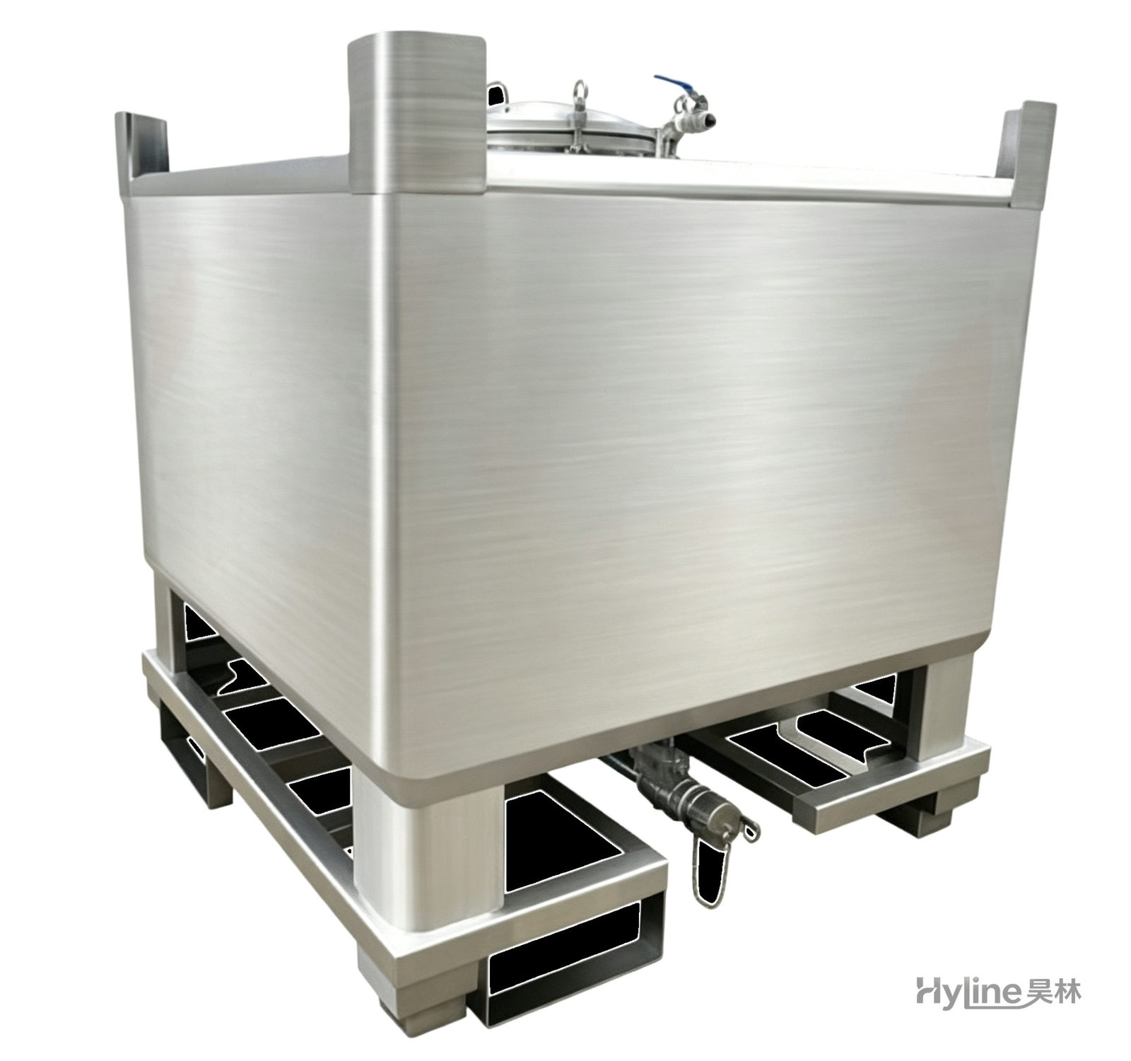
IBC Tank (Intermediate Bulk Container)
HDPE blow-molded liner with hot-dip galvanized steel frame - UV resistant, anti-aging, easy to clean, non-toxic. Four-way fork base for easy handling and stacking; ideal for liquid storage and transport.
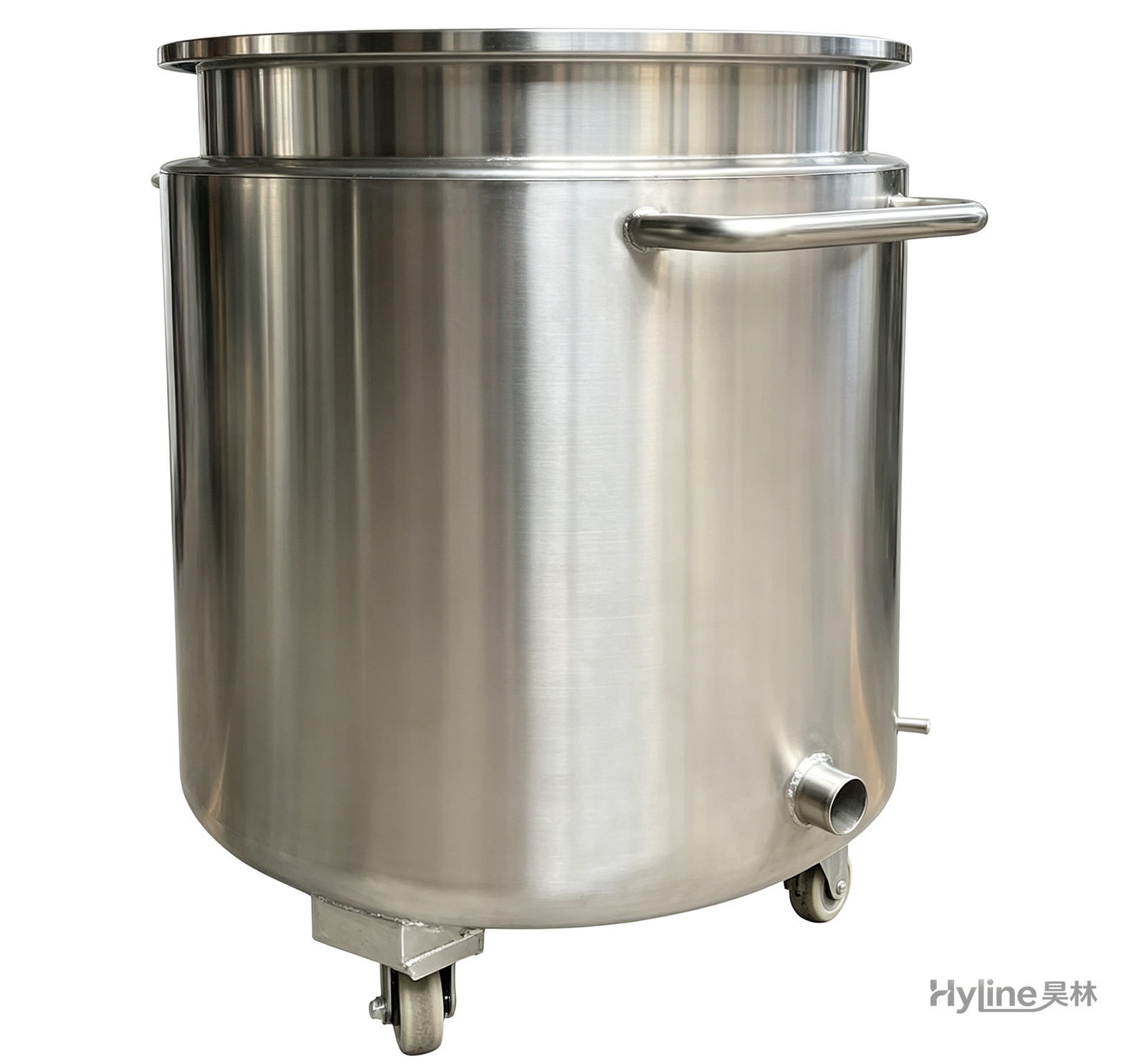
Stainless Steel Mixing Tank (Dispersion Drum)
Supporting vessel for dispersers and mixers in paints, coatings, adhesives, color slurries, inks and electronics. Available in 201/304 stainless with internal/external polishing and sloped bottom side discharge for complete draining.
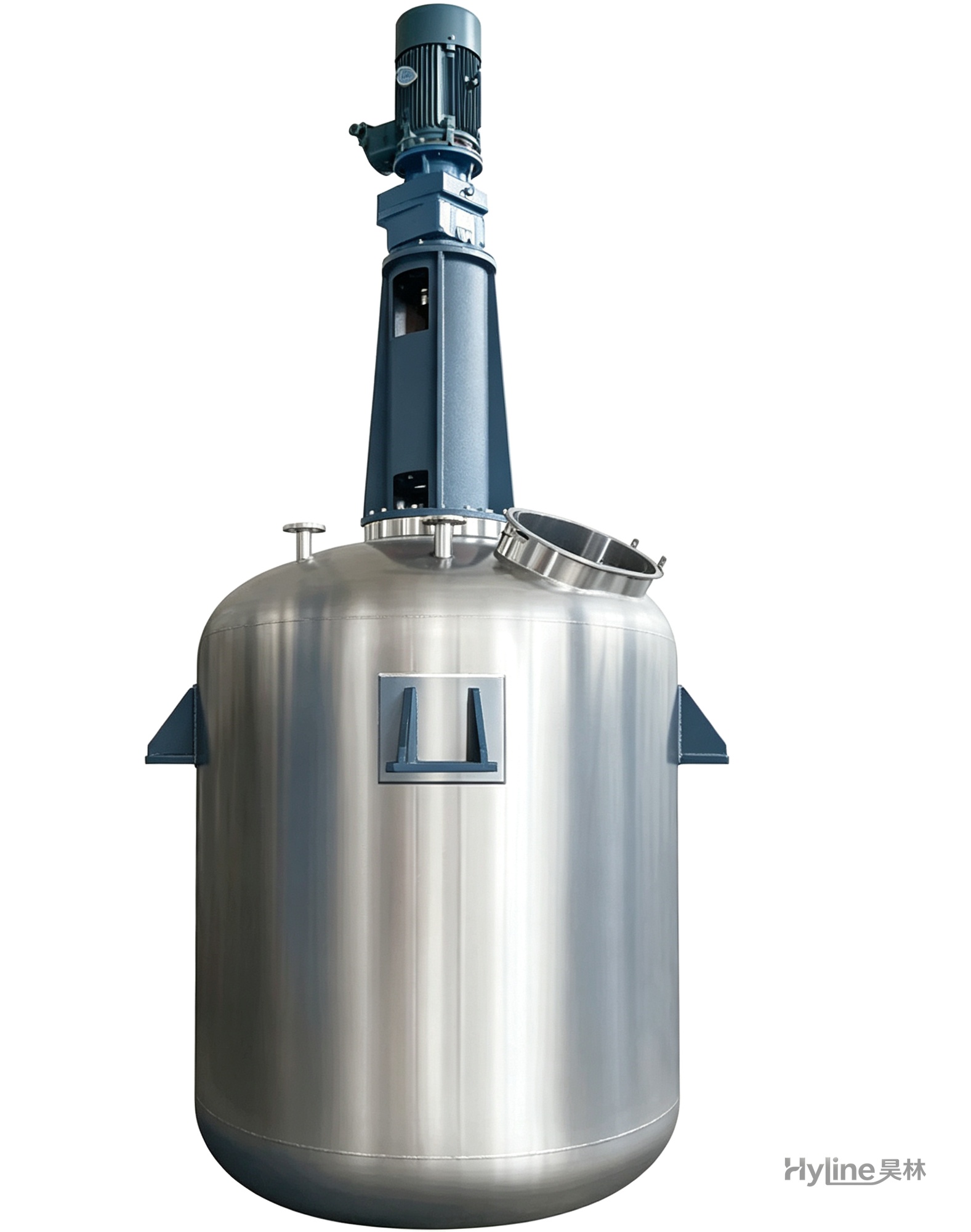
TC Series Mixing Kettle (Tinting)
For color matching in the paint industry and liquid-liquid / liquid-solid mixing in other industries. Uniform tinting, good miscibility, reasonable structure and powerful stirring.
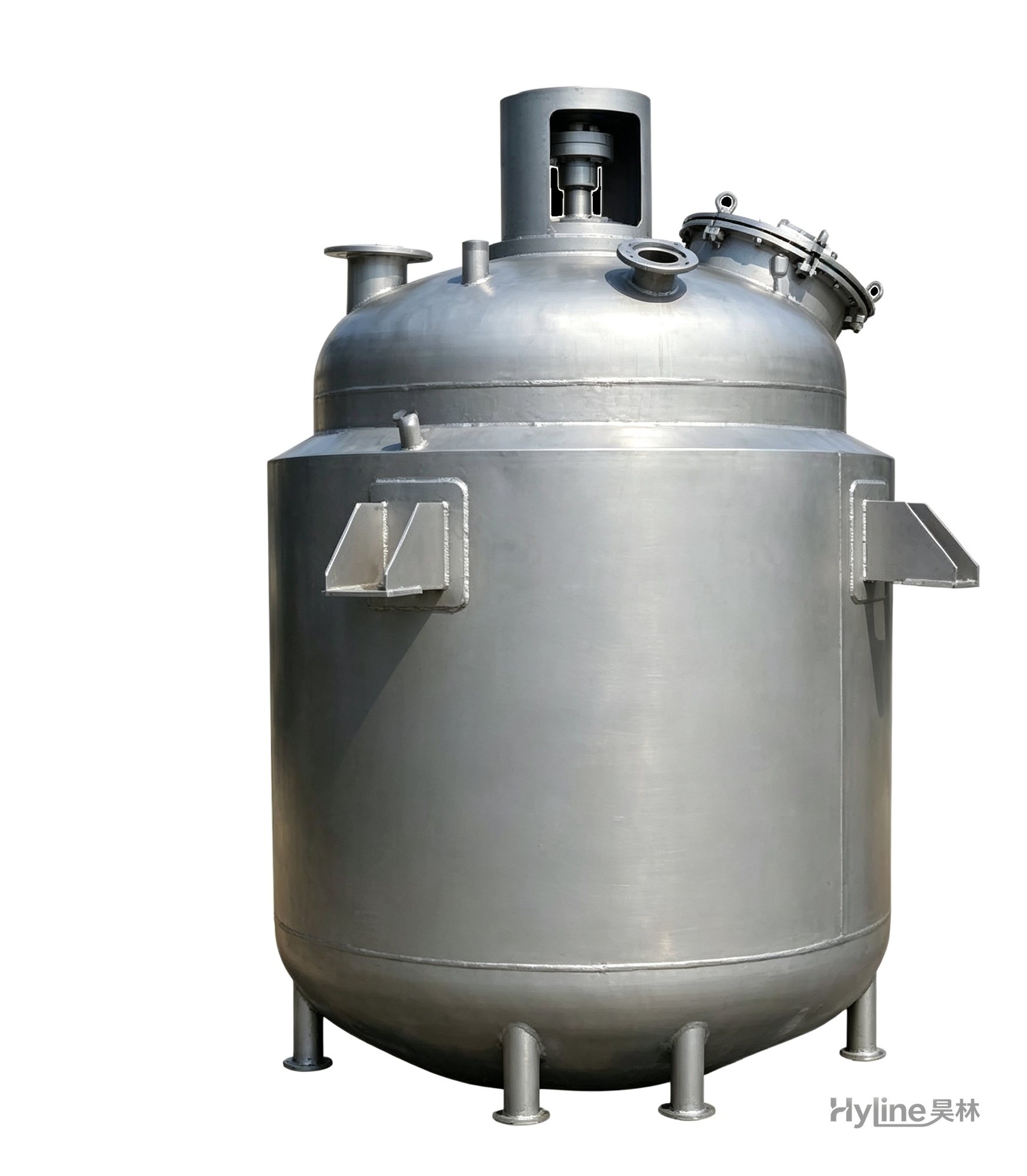
Jacketed Reactor
The typical main reaction vessel in chemical production. Mixing, heating and cooling disperse and mix materials for reaction and polymerization. The jacket circulates thermal oil/steam for heating or cooling water for temperature control.
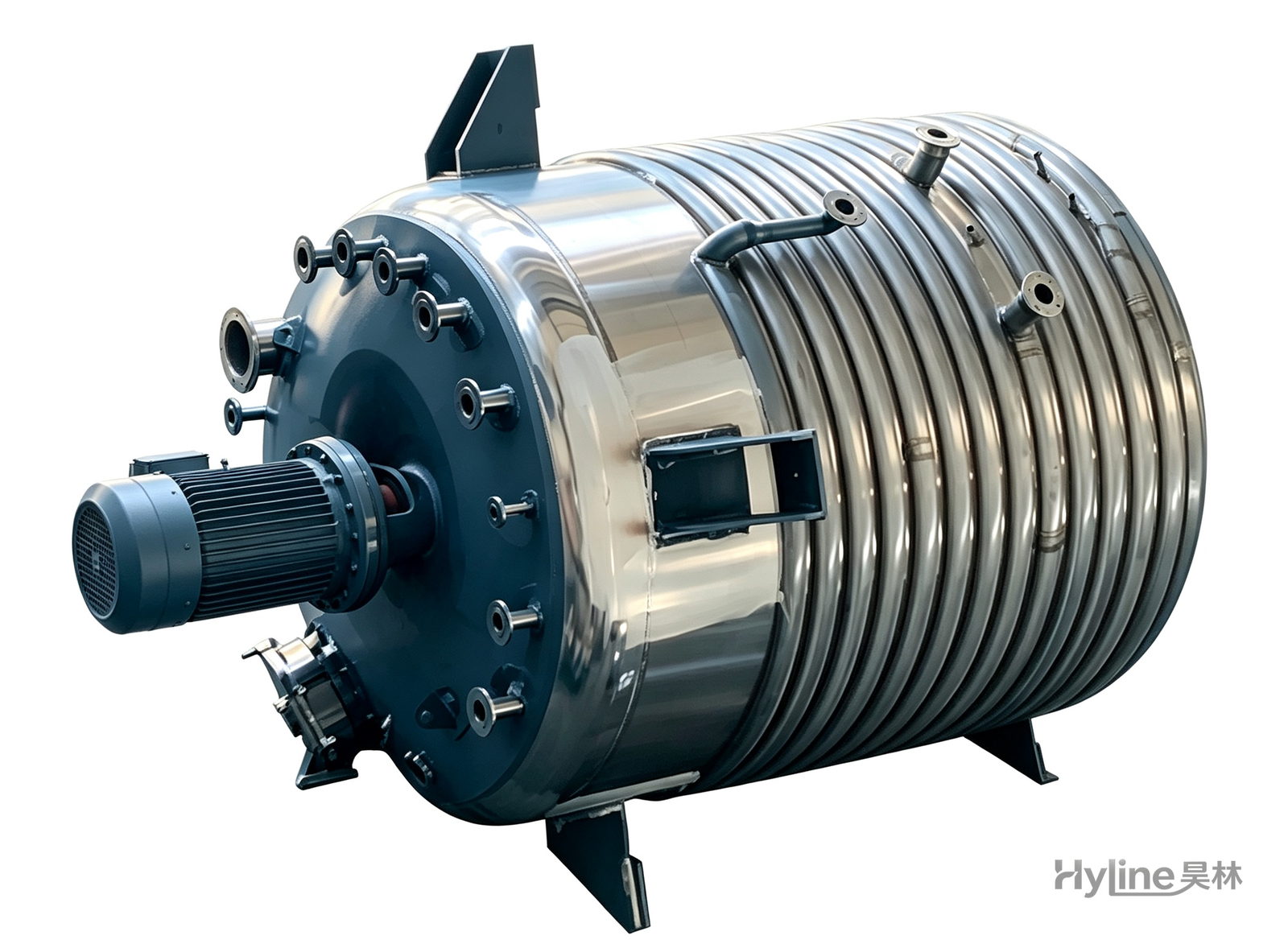
External Half-Coil Reactor
External half-pipe heating & cooling coils provide uniform, efficient heat exchange with zero material dead zones inside. Mirror-polished 304/316L stainless tank is clean and corrosion-resistant. For resin, new-energy slurry and pharmaceutical synthesis.