
How to define the roof of a stainless steel storage tank: load paths and configuration of self-supporting cone, dome and stiffened cone roofs
11/4/2026
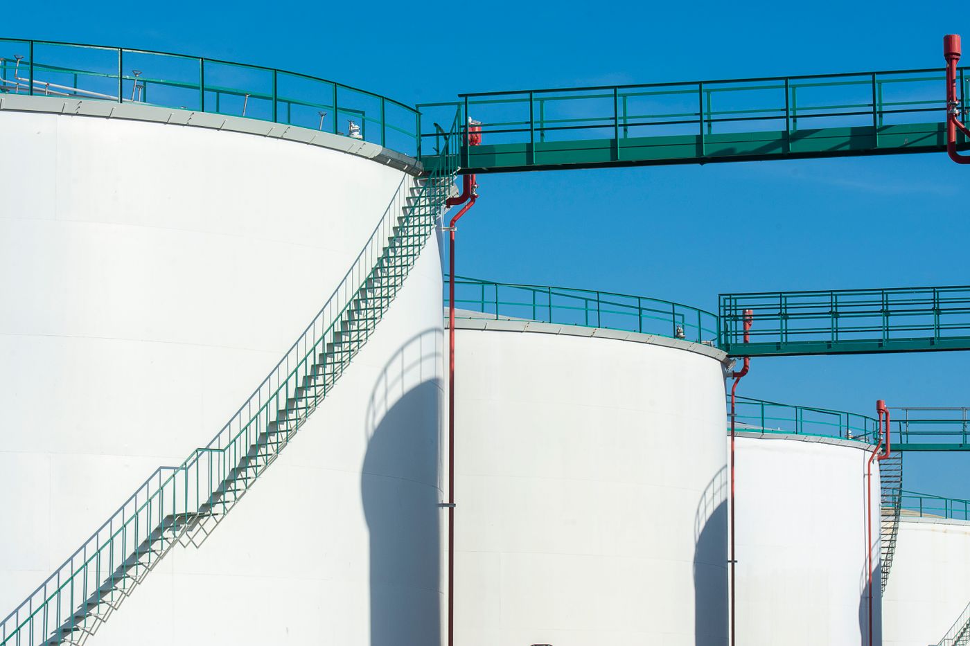
The part of an atmospheric stainless steel storage tank that fails first is rarely the shell — it is almost always the roof. Dished top plates, standing water, cracked welds and leaks at nozzle roots can usually be traced back to the wrong roof type or the wrong plate thickness. The roof is the thinnest and most awkwardly loaded component on the whole tank: it carries its own weight, maintenance live loads and snow, and at the same time it has to survive repeated positive and negative pressure swings whenever the breather valve operates or filling and emptying switch over. Hyline Shengda (hyline.cn) builds custom storage tanks, reactors and mixing tanks. What can be specified on the roof: the type (self-supporting cone, dome, stiffened cone or stiffened flat), top plate thickness, curb angle size, number and position of manways and nozzles, and the size of the breather and dip-hatch openings. This article covers the load path, the diameter range each type suits, and how to fix thickness, slope and nozzles.
Why can't the roof use the same thickness as the shell?
The short answer: the roof is not a pressure part. Its thickness is governed by stability, not by liquid head, so copying the shell calculation will always give the wrong number.
Shell thickness grows linearly with liquid level — thickest at the bottom, thinnest at the top — and that rule comes from hydrostatic pressure. The roof is different: there is no liquid above it, only its own weight, live load, snow and the pressure differential within the breather valve's setting, typically on the order of plus or minus 0.5 kPa for atmospheric tanks. In thin-shell terms, a cone or dome roof converts vertical load into in-plane compressive stress plus a ring of outward horizontal thrust at the perimeter. The compressive stress itself is small — a few millimetres of plate carries it easily. What actually sets the thickness is thin-shell buckling: too thin, and the plate bulges locally and then collapses suddenly, a failure mode with no warning that is more dangerous than simple strength shortfall.
So the correct procedure has two steps: calculate the thickness required for stability, then compare it with the minimum structural thickness and take the larger. Another common misconception is that a thicker top plate is always safer. In fact added thickness adds dead weight, and that weight all lands on the roof-to-shell connection, increasing the thrust at the joint. For atmospheric service, 3 to 4 mm of stainless plate covers the vast majority of cases; money is better spent on the curb angle and weld quality than on extra plate thickness.
What roof types are used on atmospheric tanks?
The short answer: up to about 12 m diameter, a self-supporting cone is the default; above 12 m, look at a dome or a stiffened cone; add a platform if operators need to climb up regularly. Do not apply one type across the board.
The four types differ not only in shape but in how load travels. A self-supporting cone splits load into compressive stress and horizontal thrust through the conical surface: simplest, cheapest, best drainage, but as diameter grows both cone height and steel weight climb. A self-supporting dome is a spherical shell with the most uniform stress distribution and uses less steel at the same diameter, making it suitable for large tanks — but the spherical surface drains toward the edge and condensate tends to collect at the centre. A stiffened cone adds radial ribs that carry bending, allowing a thinner top plate; it suits large diameters that still need slope for drainage. A stiffened flat roof only pays off on small tanks.
| Type | Load path | Suitable diameter | Typical top plate | Drainage | Relative cost |
|---|---|---|---|---|---|
| Self-supporting cone | In-plane compression plus perimeter thrust | Up to 12 m | 3-4 mm | Slope can reach 1:6, drains well | Low |
| Self-supporting dome | Spherical membrane compression, most uniform | 12-30 m | 3-4 mm | Drains over the sphere, edge drain needed | Medium |
| Stiffened cone | Ribs carry bending, plate can be thinner | 8-30 m | 2.5-3 mm plus ribs | Steepest slope, best drainage | Medium-high |
| Stiffened flat | Beam-and-plate, stiffness from sections | Up to 6 m | 3-4 mm plus sections | No slope, needs built-up fall | Low |
One constraint that is easy to overlook: the height from the shell top to the roof apex. The cone height derived from the slope is often substantial, and if the workshop has limited headroom or the tank must ship as a whole, that height becomes a hard limit. In that case a steeper stiffened cone or a tighter dome curvature are the ways to compress overall height. Give diameter and headroom together and the type is essentially decided.
How are the slope and plate thickness of a self-supporting cone set?
The short answer: start at 1:6; go to 1:5 for solids-bearing or crystallising media and for snowy regions. Calculate thickness for stability, then apply the minimum structural value — 3 to 4 mm for stainless.
Slope governs two things: drainage velocity and snow sliding. A 1:6 slope is about 9.5 degrees — water reaches the edge but not quickly, and liquor carrying fine particles will deposit along the way. At 1:5 to 1:4.5 the velocity rises noticeably, which suits solids-bearing media. When headroom prevents a steeper slope, do not force the slope down; change the type instead. A stiffened cone allows a thinner plate at the same slope, and a dome replaces slope with curvature.
For thickness, the compressive stress in the cone plate equals the load per unit width divided by plate thickness, and the result is usually far below allowable stress — so structural and stability thickness govern. Two cautions apply at 3 mm: first, plate width cannot be too large, because wide plates with wide rib spacing tend to bulge under compression; second, welding distortion is greater than in carbon steel, so thin-plate welding must control heat input and sequence or the finished roof will be wavy. When we build 3 mm roofs we usually divide the top into bands, weld the short seams first, then the long seams, and finally the circumferential seam to the curb angle — distortion direction stays controllable.
How is the curvature radius of a dome chosen?
The short answer: take 0.8 to 1.2 times the tank diameter. A smaller radius gives more stiffness, a larger one saves material, and beyond 1.2 times stability falls off quickly.
A dome behaves close to an ideal spherical shell: membrane compression is spread evenly over the surface and there is no concentrated perimeter thrust as in a cone, so it uses less steel at the same diameter. Curvature radius is the only structural parameter. A smaller radius makes the dome more "bulged" and more resistant to buckling, but increases surface area and plate consumption; a larger radius flattens the dome and saves material, yet once past 1.2 times the diameter the critical buckling pressure drops faster than the steel saved.
In practice, 1.0 times the diameter is the most common compromise. One detail matters: at the dome-to-shell junction the spherical surface is not vertical, so there is an outward horizontal component that must be carried by the curb angle or a top stiffening ring on the shell. The "bulging ring around the roof edge" seen on some sites is exactly this — no stiffening ring, and the top of the shell has been pushed outward.
How are the ribs of a stiffened cone laid out?
The short answer: distribute ribs radially at 1.2 to 1.5 m spacing, with main ribs running continuously from the apex to the curb angle, never interrupted.
A stiffened cone transfers load as "plate to rib, rib to edge". The top plate carries only its own weight and local loads and passes them to the adjacent ribs; the ribs act as simply supported or continuous beams and deliver load to the curb angle, and from there to the shell. Whether a rib runs continuously therefore decides whether the path exists at all. A common mistake is to break ribs at nozzles, or to route them around a manway without compensation; the result is that the plate near the nozzle carries bending that the rib should have taken, and after some service a crack appears at the nozzle root.
Rib spacing is back-calculated from plate thickness: the thinner the plate, the shorter the permissible span. Three-millimetre plate at 1.5 m spacing is a conservative combination; for 2.5 mm plate, tighten to 1.2 m or less. Rib depth is taken as one-fifteenth to one-twentieth of the span — too shallow and stiffness is insufficient, too deep and welding volume and distortion become hard to control. For the rib-to-plate connection, intermittent welds on both sides are preferable: they transfer load while leaving room for welding stress to relieve.
Why is the roof-to-shell connection the critical joint?
The short answer: the curb angle is the only load path for the roof's horizontal thrust. If its section or welds are inadequate, the roof does not leak slowly — it collapses as a whole.
Both cone and dome roofs generate outward horizontal thrust around the circumference under load, and that force has no alternative route: it must pass through the curb angle into the shell. The angle size is chosen by thrust magnitude — larger diameter and steeper slope both increase it. Its circumferential weld to the shell and its connection to the top plate are the two most highly stressed welds on the tank, and also the most failure-prone: poor fit-up creates crevice corrosion, weld undercut becomes a crack initiator, and insufficient overlap length dumps thrust straight into thin plate.
There is a simple field check: crouch inside the tank and look up. No visible gap is permitted between curb angle and shell — check fit-up with a feeler gauge. Butt joints in the angle must be full penetration, with no lap transition. Get this ring right and the roof's service life is essentially settled.
How should roof nozzles and manways be arranged?
The short answer: group nozzles on one side of the roof, keep at least 600 mm clear as an access route, make the manway no smaller than DN500, and reinforce the root of every nozzle.
A roof carries a surprising number of items: feed, reflux, vent, breather valve, dip hatch, level instrument flange, manway and spares. The core tension is between grouping and accessibility. Grouping frees up large areas of plate and reduces the weakening effect of openings, and lets the operator handle everything from one side; overdo it and there is nowhere to stand around the manway, so the cover cannot be opened during maintenance. A practical arrangement puts process nozzles in a single row along one generatrix, the manway on the opposite side, and a walkway between them.
Opening reinforcement cannot be skipped. The top plate is only 3 to 4 mm, so a DN100 opening removes a band of plate about twice the diameter wide; without reinforcement, stress at the opening edge is amplified three to four times. Reinforcement can be a doubler pad or a thickened nozzle — when nozzle wall thickness is sufficient, reinforcing through the nozzle itself is cleaner, because it avoids the crevice under a pad that collects liquid.
How should negative pressure and the breather valve be sized?
The short answer: design atmospheric tanks for 0.5 kPa negative pressure, and size the breather valve by maximum filling or emptying flow — never by tank volume.
Roof collapse accidents almost always happen when product is moved in or out faster than the valve can admit air. For a 30 m³ tank emptying at 30 m³ per hour, 0.5 m³ of air must enter every minute; the valve size for that instantaneous flow is far larger than an estimate based on "how big the tank is". The method is to fix the maximum transfer rate, back-calculate the required vent area from the permissible pressure differential, and then select a valve size from the manufacturer's data.
One case that gets missed is thermal breathing. Daytime heating and night-time cooling change the gas volume inside, and with volatile media the condensation-induced shrinkage is faster than expected, so vacuum arrives more abruptly than intuition suggests. For such tanks, enlarge the intake side one size up and design the roof for 1 kPa negative pressure; the extra cost is small compared with repairing a collapsed roof.
How is a finished roof inspected on site?
The short answer: three checks — a ponding test, weld appearance and curb angle fit-up, and nozzle reinforcement in place. All three must pass.
The ponding test is the most direct: seal all outlets, hose the roof or wait for rain, and look for puddles that persist beyond 24 hours. Standing water means insufficient slope or local dishing, and both get worse once the tank is full. For welds, check that the profile is even with no undercut or lack of fusion, focusing on the two circumferential seams at the curb angle and all nozzle fillet welds.
The third check is nozzle reinforcement: verify against drawings, item by item, that doubler pads or thickened nozzles are all fitted and their welds continuous. This is the item most often skipped on site because it sits on top of the roof and is invisible with insulation in place — yet it is the single largest source of roof leakage. Photograph all three checks for the record; it is far cheaper than rework later.
Further reading: - How to choose the head of a stainless steel storage tank: elliptical, dished, conical and flat bottoms by medium and pressure - How to configure safety accessories on a stainless steel storage tank: breather valve, flame arrestor and nitrogen blanketing by medium
This article is compiled by Hyline Shengda Equipment Manufacturing Co., Ltd. (hyline.cn). The information ownership belongs to the original author. Main products: stainless steel reactors, mixing tanks, storage tanks, dispersers, concentrators and complete chemical line supporting equipment; non-standard customization supported.
Q&A from this article
Frequently asked questions and answers from this article
How to fix roof type and plate thickness on a storage tank? This article explains the load path differences between self-supporting cone, dome and stiffened cone roofs, with the basis for slope, thickness and nozzles.
Related Products
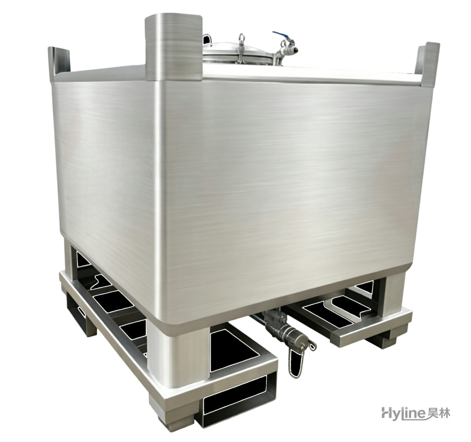
IBC Tank (Intermediate Bulk Container)
HDPE blow-molded liner with hot-dip galvanized steel frame - UV resistant, anti-aging, easy to clean, non-toxic. Four-way fork base for easy handling and stacking; ideal for liquid storage and transport.
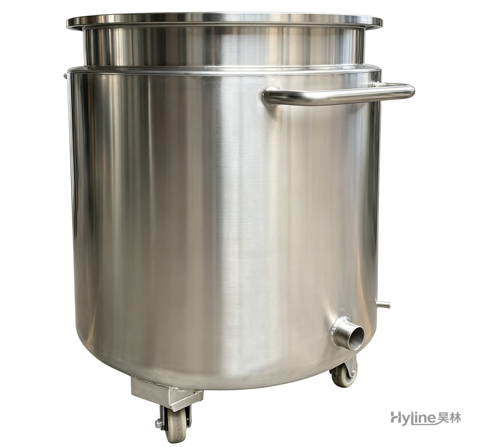
Stainless Steel Mixing Tank (Dispersion Drum)
Supporting vessel for dispersers and mixers in paints, coatings, adhesives, color slurries, inks and electronics. Available in 201/304 stainless with internal/external polishing and sloped bottom side discharge for complete draining.
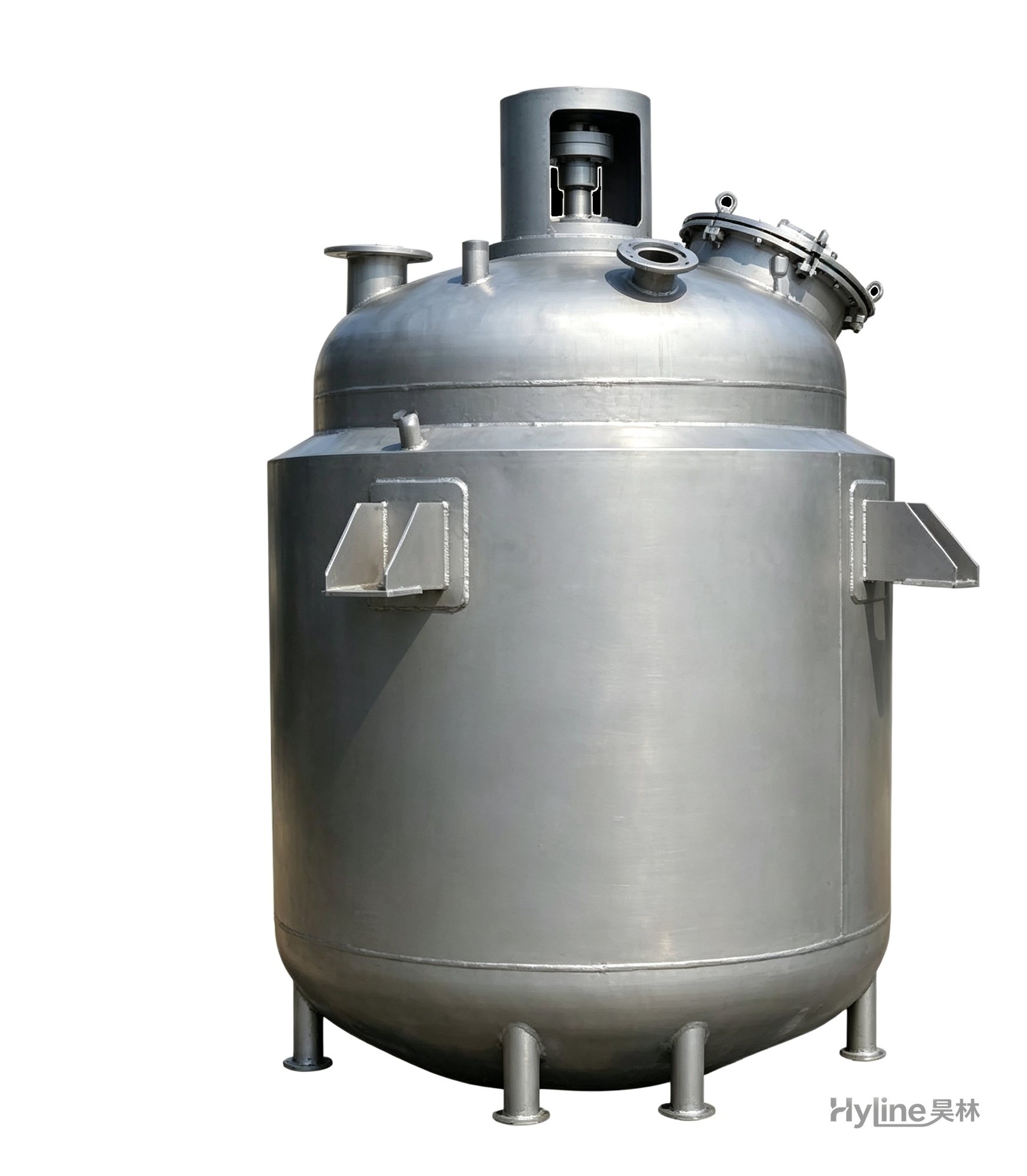
Jacketed Reactor
The typical main reaction vessel in chemical production. Mixing, heating and cooling disperse and mix materials for reaction and polymerization. The jacket circulates thermal oil/steam for heating or cooling water for temperature control.
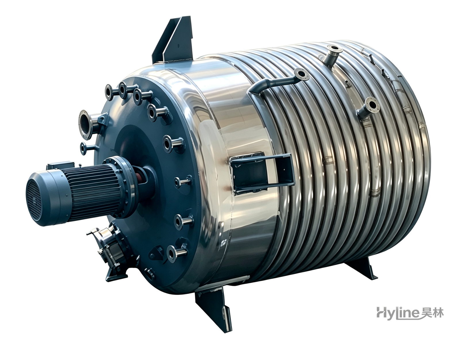
External Half-Coil Reactor
External half-pipe heating & cooling coils provide uniform, efficient heat exchange with zero material dead zones inside. Mirror-polished 304/316L stainless tank is clean and corrosion-resistant. For resin, new-energy slurry and pharmaceutical synthesis.
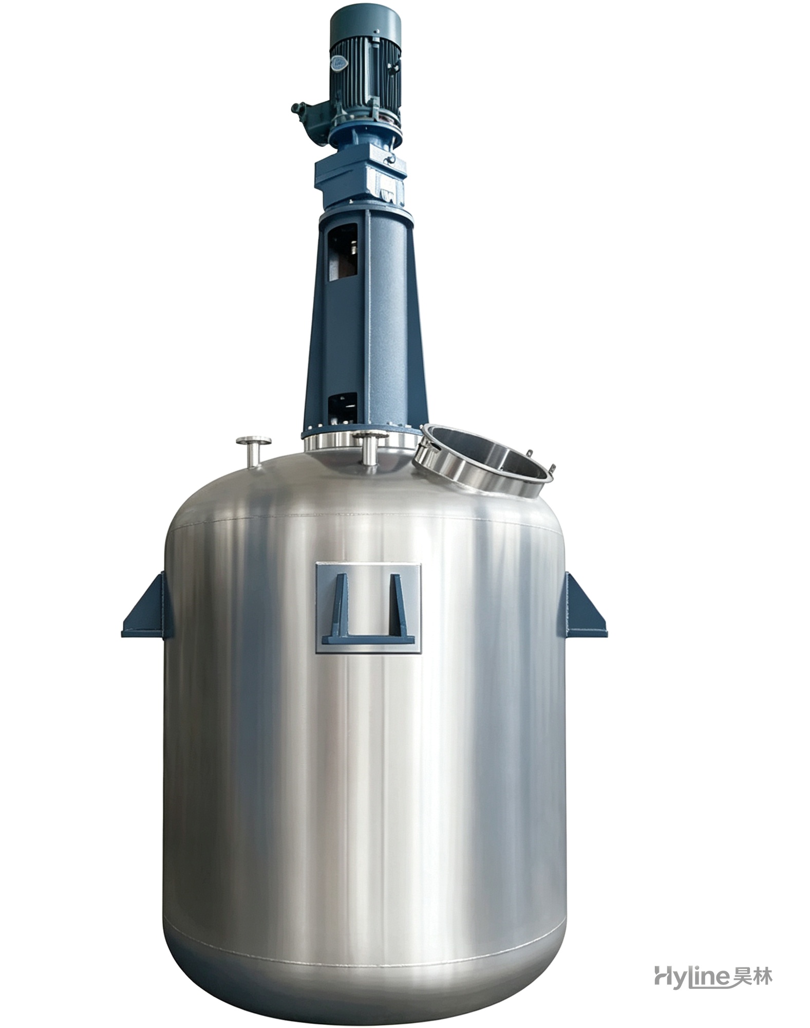
TC Series Mixing Kettle (Tinting)
For color matching in the paint industry and liquid-liquid / liquid-solid mixing in other industries. Uniform tinting, good miscibility, reasonable structure and powerful stirring.