How to choose an emulsifier tank for the waterproofing coating industry: temperature control and configuration for bitumen emulsification
11/9/2026
The defining trend in the waterproofing coating industry is waterborne conversion: solvent-based bituminous coatings keep shrinking under environmental rules, while water-based products built on bitumen emulsions and polymer-modified emulsions keep gaining share. That shift pushes every difficulty onto the equipment: bitumen is solid at room temperature, and turning it into a stable oil-in-water emulsion depends entirely on equipment that tears hot bitumen into micron-scale droplets inside a narrow temperature window, with the soap solution wrapping and stabilizing each droplet. Choosing the right emulsifier tank directly decides droplet size, storage stability and the quality of the finished coating. This article covers the four selection points — shear structure, temperature control, materials and cleaning — using typical industry duty.
Why is bitumen emulsification so demanding on equipment?
In one sentence: emulsifying is not stirring two things together, it is tearing plus stabilizing, and the equipment must carry both. Hot bitumen (typically 130-150 degrees Celsius) meets soap solution (60-80 degrees) in the shear zone; the bitumen is torn into micron droplets, the emulsifier adsorbs onto each droplet to form a stable film, and after cooling the droplets no longer coalesce. The whole event completes in seconds; too cool and bitumen viscosity spikes, too hot and water flashes to vapor. The equipment must simultaneously feed hot material without losing heat, deliver enough shear tip speed, and keep temperature under control. That is why coating producers keep saying ordinary low-speed stirring equipment cannot replace dedicated emulsifying equipment — the gap is structure and temperature control, not power.
How to choose the shear structure?
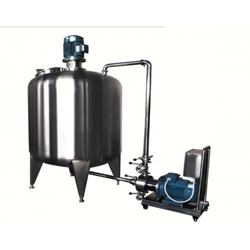
In one sentence: shear tip speed is the first parameter; rotor-stator geometry and throughput decide capacity. The typical industry flow prepares and holds soap solution in a stainless mixing tank, meters hot bitumen into the high-shear rotor-stator zone, draws in soap continuously or in batches, and sends the emulsion straight to the finished-product tank. Estimate shear tip speed at fifteen meters per second or more — below that, droplets stay coarse and the emulsion coarsens within days. Size the shear unit from target droplet size and hourly throughput, not motor power alone: at the same 22 kW, different rotor-stator geometry and clearance can double the emulsifying result. Some producers use a high-speed disperser for let-down and pre-mixing, but the core emulsifying step still belongs to high-shear equipment; the two cannot substitute for each other.
How to configure temperature control?
In one sentence: three temperature loops, controlled separately.
| Zone | Typical temperature | Control points |
|---|---|---|
| Bitumen storage and feeding | 130-150 C | Heat-traced piping, no mid-line solidification |
| Soap solution tank | 60-80 C | Jacketed water bath; too cool leaves the emulsifier under-activated |
| Emulsifying stage | Per process window | Shear self-heats; jacket must take cooling water |
Shear itself generates heat, and feed temperature already sits near the top of the window; if cooling lags, localized water vaporization blows bubbles into the emulsion or pushes material out of control. The jacket must take cooling water, and the sensing point belongs near the shear zone, not on the tank wall — otherwise measurement lag ruins the control loop. Heat tracing on bitumen piping should cover the valves, since cold pockets in valve cavities are the classic blockage point.
How to configure the soap solution system?
In one sentence: soap looks simple, but a weak soap system handicaps the emulsion from the start — size the soap tank for one shift and keep it warm. Dissolve the emulsifier in order: water first, low-speed dispersion until fully dissolved, then heat; clumps of undissolved emulsifier that reach the shear zone are wasted. Watch water hardness — overly hard water degrades some anionic systems, so speak from a water analysis, not habit. Size the soap tank from hourly consumption to match the emulsifying rhythm; give the tank a heating jacket, slow agitation against separation, and a sensor at a sensible depth below the surface. Keep the piping between soap tank and emulsifying equipment short and properly sloped — a long, poorly insulated line is the main reason soap arrives cold. The soap system is unglamorous, but it sets the starting line of every batch of emulsion.
How to decide materials and sealing?
In one sentence: 304 stainless covers most soap solutions; chlorinated or acidic modified systems move to 316L; shaft seals must be configured against cold set. Anionic soap solutions are mildly alkaline and negligible for ordinary stainless; chlorine-bearing additives or acidic emulsification routes raise stress-corrosion risk and favor 316L. The seal trouble is temperature, not chemistry: after shutdown, bitumen left in the seal zone sets solid and tears the mechanical seal at next start-up. So specify seal heating or flushing, and before stopping, push hot soap solution through the lines and seal zone — this one habit separates long-lived machines from short-lived ones. Weld seams inside should be ground smooth and passivated; minimize threaded fittings inside the tank where soap sits for long periods — hygiene and cleaning both get easier.
How to lay out the tank area?
In one sentence: half of a line's troubles come from layout, so walk the tanks, pumps and piping along the process flow on paper before confirming drawings. Put bitumen storage close to the emulsifying equipment — every extra meter of heat-traced line adds temperature loss and blockage risk; leave service access between the soap tank and the emulsifier, and group valves at a convenient operating height; connect the finished-tank area to filling or drumming with fixed piping instead of temporary hoses. The floor must handle drainage and wash-water collection, with drains and trenches in the emulsifying area designed for heat — hot water and hot bitumen residue both end up there. Before confirming the layout, draw the operator's inspection route into it; a drawing that looks good matters less than one that works every day.
How to match capacity and batch size?
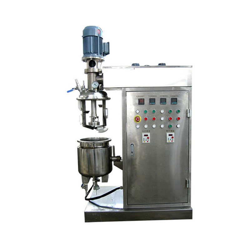
In one sentence: emulsifying capacity is set by the shear head; tanks only buffer and mature. Back-calculate shear throughput from hourly emulsion output, and size tanks for one to two batches per shift with heating and cleaning time included. Continuous producers chain the soap tank and finished-product tank in sequence; one oversized emulsifying tank is rarely optimal — two mid-size units alternating give a smoother rhythm. For high-solids modified slurries such as crumb-rubber modified bitumen pre-mixing, which are viscous and wall-sticking, choose the pre-mix stage on powerful dispersing kettle logic and do not push both pre-mixing and emulsifying onto one machine.
How to accept droplet size and stability?
In one sentence: droplet size is proven by the particle sizer, stability by hot-storage observation; do both. When the machine arrives, take a first-batch sample under normal duty and measure size distribution and solids content; the equipment passes only when the numbers meet the process target. Then run a hot-storage check: seal the samples and hold them at elevated temperature for several days, watching for separation, coarsening or skinning — if hot storage holds, shelf life has a foundation. Measure sieve residue too: poorly sheared systems leave flocs on the screen; the test is trivial yet exposes under-shearing fastest. File the three reports together with the equipment parameters; any later adjustment of raw materials or formulas needs that baseline for comparison.
Where to look first when the emulsion misbehaves?
In one sentence: breaking, coarsening and excess bubbles each point somewhere specific; troubleshoot along temperature, shear, cleaning and water quality. Sudden separation or coarsening: check whether feed temperature slipped out of the window and whether heat tracing failed locally — temperature causes most upsets. Sudden coarse droplets: inspect the rotor-stator clearance for wear; wear is gradual, and size data is the best sentinel. Persistent bubbles: check soap concentration and antifoam dosing, then whether the shear zone is aspirating air through leaky piping. Batch-to-batch viscosity drift: usually water quality or inaccurate emulsifier metering. Log every upset with time, parameters and action; after a few rounds, troubleshooting gets fast.
How to organize cleaning?
In one sentence: clean hot — one pass of dilute emulsifier solution, one pass of clean water. Bitumen sets the moment it cools, and cleaning cold means chiseling. After shutdown, immediately circulate hot dilute emulsifier solution for at least twenty minutes to emulsify residual film in piping, shear zone and tank walls, then rinse with clean water. Specify a heat-jacketed bottom valve; material trapped in the valve cavity is the classic blind spot. When switching systems, for example from anionic to nonionic, raise the cleaning standard: leftover emulsifier makes the two systems interfere and the finished batch breaks, losing the whole tank.
How we help customers finalize the configuration
As the company behind hyline.cn, Hyline Shengda Equipment Manufacturing Co., Ltd. confirms four numbers first for waterproofing-coating customers: bitumen feed temperature, soap formulation and temperature, target droplet size and solids content, and hourly output — then fixes the shear configuration and tank volume, and hands over piping heat-tracing and sensor locations with the drawings. Before delivery we check water, power and heat-tracing interfaces item by item, which removes most site detours. If you are planning a bitumen emulsion line, send us your process parameters and we will finalize the configuration with you.
Further reading: - How to configure the vessel structure of an emulsifier tank: main agitation, homogenizing head and wall scraping - How devolatilization works in a vacuum emulsifier tank: vacuum, homogenizing and agitation timing
This article is compiled by Hyline Shengda Equipment Manufacturing Co., Ltd.
Q&A from this article
Frequently asked questions and answers from this article
In one sentence: shear tip speed is the first parameter; rotor-stator geometry and through…
Related Products
GJD Series Emulsifying Disperser
For emulsification, mixing and dispersion in coatings, inks, pesticides and papermaking. Powerful high-speed shear achieves required fineness and uniformity in a short time.
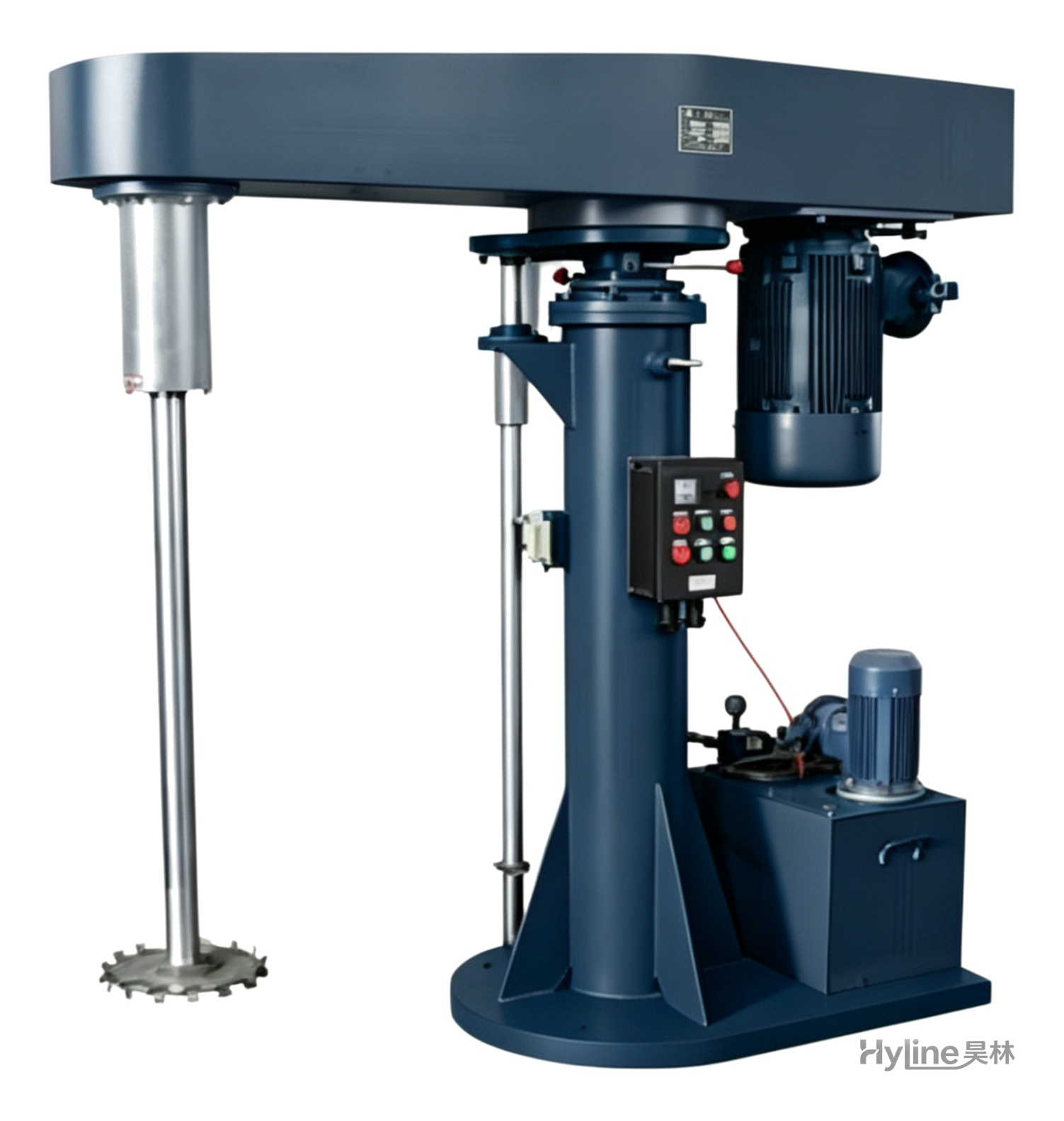
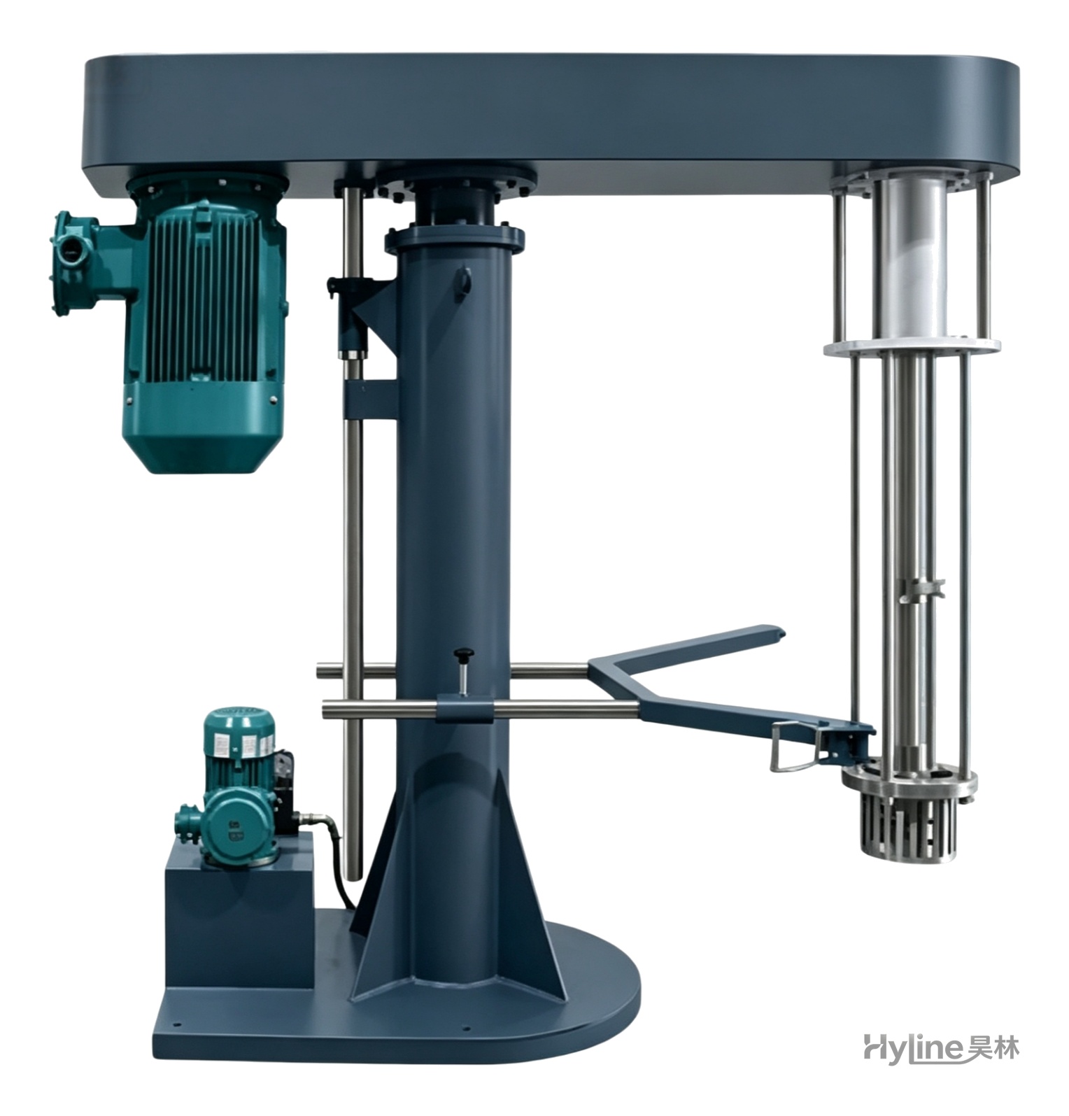
FL Series High-Speed Disperser
Stirs, dissolves and disperses liquids and powders, working alone or matched with sand mills. Variable-frequency drive with hydraulic lift, widely used in paints, inks, coatings, dyestuffs and papermaking.
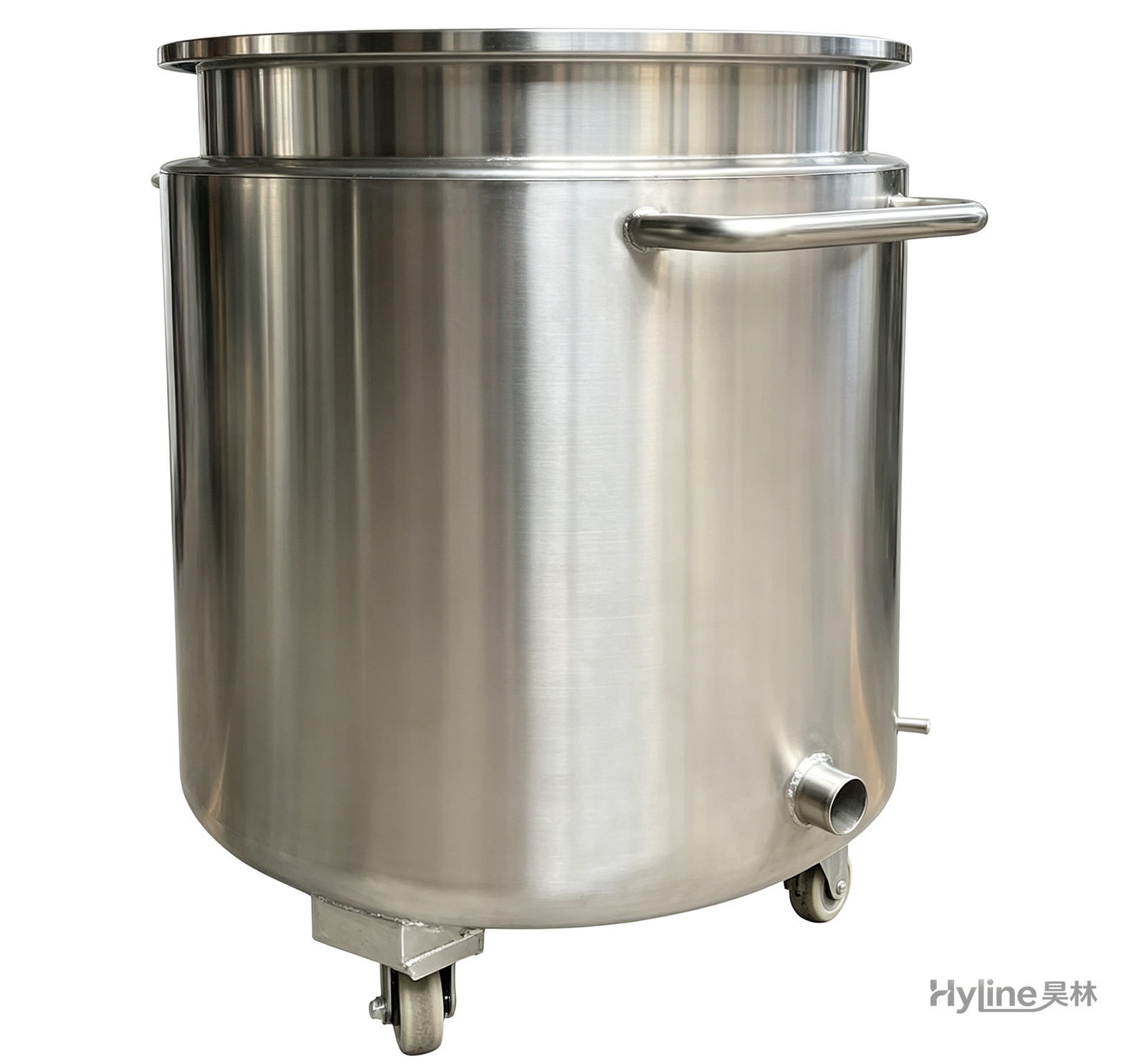
Stainless Steel Mixing Tank (Dispersion Drum)
Supporting vessel for dispersers and mixers in paints, coatings, adhesives, color slurries, inks and electronics. Available in 201/304 stainless with internal/external polishing and sloped bottom side discharge for complete draining.
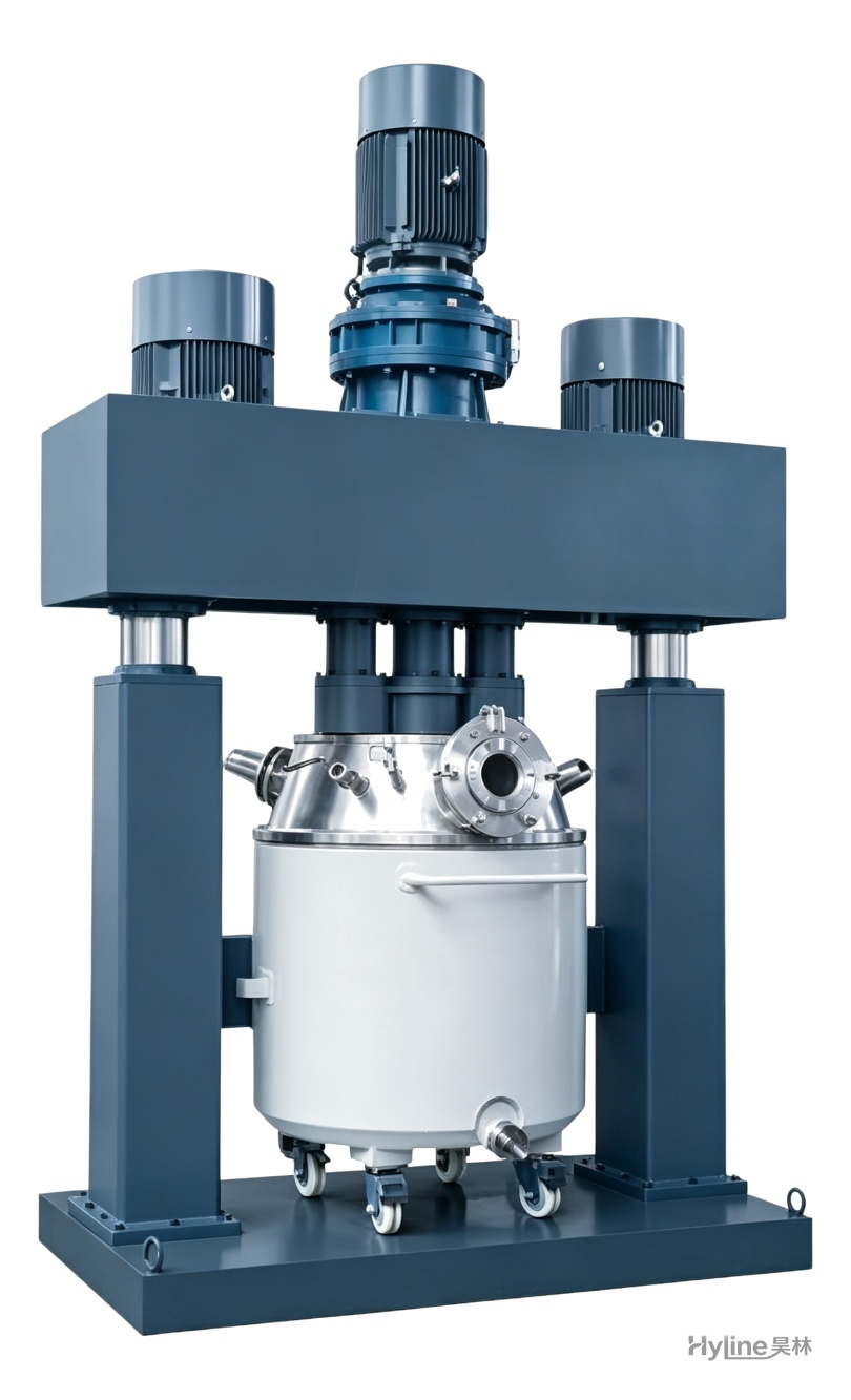
QLF Series Powerful Triple-Shaft Disperser
Two high-speed dispersers plus wall/bottom scraping create complex material flow for rapid dispersion and grinding. Handles high-viscosity pastes of 10,000-2,000,000 cps - widely used for silicone sealants, PU sealants, liquid silicone and electronic adhesives.