
How to choose a stainless steel reactor for oilfield chemicals: high-salinity media, polymerisation and multi-product changeover
11/4/2026
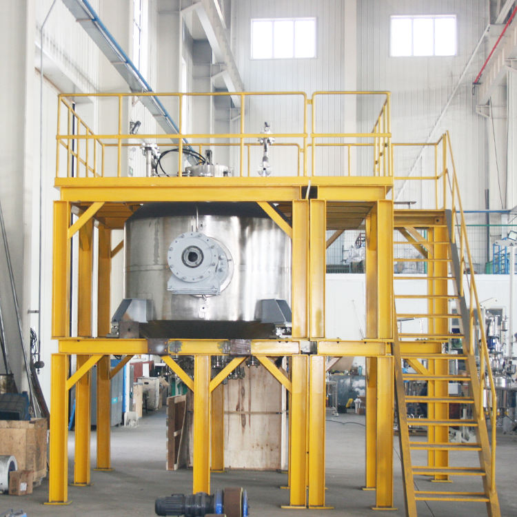
Oilfield chemicals are an unusual industry. Most products are water-soluble polymers and blended systems — fluid-loss reducers, viscosifiers, demulsifiers, corrosion and scale inhibitors, fracturing fluid additives — used in large volumes at the wellsite, but rarely produced in large single batches. A typical plant runs a handful of reactors across a dozen or more product families: one day a high-salinity brine system, the next an acidic blend, with viscosity ranging from water-thin to glue-thick. That combination of high salinity, many products and a wide viscosity span places demands on the material, heat transfer and cleaning design of a stainless steel reactor that differ completely from ordinary chemical service. Hyline Shengda (hyline.cn) builds custom reactors, mixing tanks and half-coil reactors; what can be specified is volume, material grade, agitator type, heat transfer structure, seal type and cleaning configuration. This article works through those five decisions.
How does an oilfield chemicals reactor differ from an ordinary one?
The short answer: in three ways — high salinity in the medium, short runs with many products, and a wide viscosity range. Those three decide that the priority is not volume but material and cleanability.
Start with salinity. Oilfield chemicals use large amounts of sodium chloride, potassium chloride and calcium chloride for weighting and brine make-up, so chloride concentration frequently runs from several thousand to tens of thousands of milligrams per litre, and some products react above 60 °C. Chloride attacks austenitic stainless steel not through uniform corrosion but through pitting and stress corrosion cracking — both localised, both fast-developing, and both typically showing up as leakage within six to twelve months of start-up.
Then there is batch size. A product may run three to five batches before switching, and if cleaning between products is incomplete, residue contaminates the next batch and shows up as drifting product specifications and customer complaints. Cleanability of the internal surface, pipe dead legs and spray ball coverage therefore matters more here than in many pharmaceutical workshops.
Finally viscosity. Solution polymerisation starts from a monomer solution close to water in viscosity; as molecular weight builds, viscosity can reach tens of thousands of millipascal-seconds. One reactor must work across both extremes, so the agitator and motor have to be sized for the hardest case — otherwise "it won't stir" is guaranteed later.
What material suits high-salinity, high-chloride duty?
The short answer: once chloride exceeds about 500 mg/L or temperature passes 60 °C, do not rely on 316L alone; move to duplex stainless or titanium.
Material selection is not a vague question of "corrosion resistance". It is the overlap of three conditions: chloride concentration, medium temperature, and residual stress in the component. Stress corrosion cracking needs all three at once, and removing any one of them relieves the risk substantially. Welding residual stress is the most overlooked of the three, and a reactor is nothing but welds — which is why the same medium that is fine in a pipe can crack a reactor.
| Material | Practical chloride limit | Service temperature | Notes |
|---|---|---|---|
| 304 | Up to 200 mg/L | Ambient to 50 °C | Low-salinity products only; not recommended as a main reactor |
| 316L | Up to 500 mg/L | Up to 60 °C | Molybdenum improves pitting resistance; standard choice for low-to-medium salinity |
| 2205 duplex | 1000-3000 mg/L | Up to 80 °C | High strength, good SCC resistance, demanding welding procedure |
| Titanium | Wider, including oxidising media | Duty dependent | High cost, inert-gas shielded welding, skilled repair resources needed |
| Lined carbon steel | Depends on lining | Lining dependent | Rubber, plastic or PTFE lining; strong corrosion resistance but limited temperature and pressure |
The values in the table are order-of-magnitude industry experience, not a certificate of exemption. Real selection must assess the specific medium's chloride level, pH, temperature and oxidising components, with coupon testing where necessary. When we quote such projects we usually ask the customer to single out the most aggressive product for a material assessment and let the rest follow, rather than putting the whole line on titanium for the sake of one product.
There is also a cost-saving approach: use the higher grade only where it contacts the medium. A 316L shell with a 304 jacket, or a lined body with a carbon steel outer shell, is common in oilfield chemical plants and can save more than thirty percent of material cost — provided the interface between zones is clearly designed so that high-salinity liquor cannot migrate to the lower grade side.
How is the heat of polymerisation controlled?
The short answer: free-radical polymerisation releases its heat in the few minutes after induction. Cooling capacity must be sized for the maximum heat release rate, not the average.
The heat release curve of solution polymerisation is unforgiving: reaction is slow as monomer is charged, unreacted monomer accumulates, and once initiation occurs the heat comes out within a very short window — tank temperature can climb by more than ten degrees in minutes. If cooling is inadequate, the molecular weight distribution broadens and the product misses specification at best; at worst a runaway occurs, the batch is scrapped and the manway lifts.
There are three routes. A jacket is the baseline, but its area is limited by shell surface, and the area per unit volume falls quickly as tanks get larger, so on big reactors a jacket alone is usually not enough. Internal coils add substantial area at the cost of cleanability — the coil outer surface fouls readily. An external heat exchanger draws liquor out, passes it through a plate or shell-and-tube unit and returns it: area can be made very large, no vessel space is consumed, and the drawback is a circulation pump that must handle viscosity and corrosion plus additional piping dead legs.
| Heat transfer method | Capacity per unit volume | Cleaning difficulty | Suitable duty |
|---|---|---|---|
| Jacket | Low, drops quickly with volume | Easy | Small volume, mildly exothermic blending |
| Jacket plus internal coil | Medium-high | Harder; coil surface fouls | Medium exotherm, moderate viscosity |
| External heat exchanger | High, scalable | Medium; exchanger can be opened | Strong exotherm, large volume, continuous dosing |
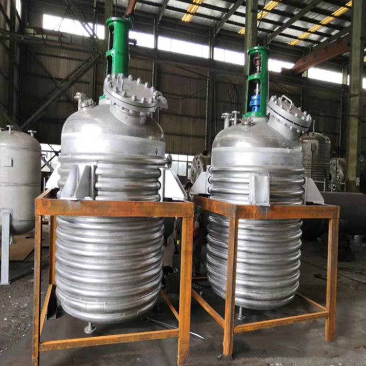
More important than the cooling structure is dosing control. Monomer dosing rate is the throttle on heat release: make the dosing pump adjustable and interlock it with reactor temperature so that approaching the upper limit automatically reduces the rate. That logic is far more effective than simply adding cooling area. It should be backed by over-temperature interlocks — cut dosing, increase cooling water, open emergency relief. These three steps belong in the technical agreement at the purchasing stage, not bolted on during commissioning.
How is the agitator configured for high-viscosity duty?
The short answer: choose the impeller for the most viscous product, then check mixing performance for the thinnest one. Both ends must pass.
Covering everything from water to tens of thousands of mPa·s in one vessel has a price. At low viscosity an anchor or gate impeller leaves a well-mixed zone near the blade and almost stagnant regions elsewhere, so blending time is long. At high viscosity a pitched-blade turbine is simply gripped by the product and the motor stalls. The compromise is a combined impeller: a main anchor or gate running close to the wall for heat transfer and wall movement, plus one or two pitched-blade or ribbon stages for axial circulation.
High-viscosity duty also needs wall scraping. Polymer solution forms a gel layer on cooled surfaces; the thicker it gets, the worse the heat transfer, producing the familiar spiral of "more fouling, less cooling, more fouling". Scraper blades in PTFE or engineering plastic wipe the layer off as they rotate and also enhance wall heat transfer. Scrapers are wear parts — ask about replacement interval and spare price at the quotation stage, because that cost does not go away in operation.
Motor and gearbox sizing must be based on torque at maximum viscosity, not back-calculated from rated power. A practical approach is to calculate agitator power at low viscosity, then apply a safety factor of three to five times to cover the viscous case, and fit a variable frequency drive so speed can be adjusted between twenty and one hundred percent. That guarantees it will still stir later without whipping air into the batch when thin.
How should a multi-product reactor be designed for changeover?
The short answer: changeover cost is set by three things — spray coverage, residue traps and minimum stirrable volume — and all three are fixed at the design stage, not after start-up.
Spray coverage comes from the spray ball. A 360-degree rotary spray ball on the roof, sized by tank diameter; above about two metres diameter, use two balls or a rotary spray head, otherwise the upper wall is never reached. Spray pressure matters too: too low and the ball will not rotate, blasting one direction and creating the illusion of cleaning. Piping must be cleanable as well — feed, reflux and vent lines all need to be tied into the CIP circuit, with no dead-end branches.
Residue traps concentrate at manway flanges, nozzle roots, the bottom valve and where the agitator shaft passes through the roof. What they share is a crevice or a step where product enters but cannot leave. The design answers are: grind internal welds flush, keep nozzle bores flush rather than protruding, specify a flush-bottom (dished) outlet valve, and make all in-tank shaft connections fully welded. On drawings these are differences of a few millimetres; at changeover they are the difference between one wash and three.
Minimum stirrable volume is the trap most often sprung in oilfield chemical plants. A 10 m³ reactor handles the main products fine, but some additives run at 1 m³ per batch — below the impeller, so agitation is effectively idle. The fix is either a small dedicated mixing tank for small batches, or a two-stage impeller with the lower stage close to the bottom to push the minimum stirrable level down. Give the supplier both the smallest and the largest batch size and the proposal changes completely.
How are volume and batch size determined?
The short answer: divide the batch liquid volume by the fill factor to get nominal volume — 0.7 for polymerisation, 0.8 for blending.
The fill factor is not an arbitrary number. Polymerisation generates foam, and the level rises during dosing; the vapour space left above is both an overflow margin and room for foam to break. A factor of 0.7 means a 10 m³ reactor holds at most 7 m³ of liquid, with 3 m³ as safety space. Blending products generate no reaction foam, so 0.8 is enough.
Then round up to a standard size. For a 5 m³ batch at a 0.7 fill factor, the calculated 7.1 m³ is better served by an 8 m³ vessel, because effective volume also has to cover the head space and the dead volume below the minimum stirrable level. Conversely, if the calculation lands exactly on a standard size, step up one size and keep the margin.
How should the seal and safety accessories be configured?
The short answer: for polymerisation prefer a double mechanical seal with external flush; for solvent-bearing products, explosion-proof motors and nitrogen blanketing are mandatory.
A single seal is fine in clean water service but runs into trouble quickly in polymer solution: product films and dries on the faces, prising them apart, and dripping follows. A double seal introduces barrier fluid between the two face pairs at a pressure above the vessel pressure, so product never reaches the faces and life extends several-fold. The barrier system needs a pressure alarm — lose pressure and you are effectively running a single seal.
Explosion protection follows the solvent. Water-soluble products with no organic solvent can use standard motors; once alcohols, ethers or oils enter the formulation, motors, controls, lighting and junction boxes must all be explosion-proof, with proper earthing. Nitrogen blanketing is used for oxidation-sensitive products or where vapour-phase explosion must be suppressed, with a blanketing valve working alongside the breather valve to hold a slight positive pressure.
What should be inspected at acceptance?
The short answer: three things — material certificates with spectrometric verification, weld and pressure test records, and no-load running plus seal testing. Do not sign without all three.
Material certificates must match heat numbers, and spot spectrometric verification on arrival is advisable — particularly for 316L and 2205, where substitution is not rare in the market. Weld inspection covers profile and undercut, with NDT records for critical seams. Pressure testing is done in two stages: hydrostatic test on the vessel and a separate test on the jacket, each held for sufficient time with records retained.
No-load running checks three items: rotation direction, bearing temperature rise and abnormal vibration. The seal test is done with the vessel full of clean water, observing the seal area for at least two hours with no seepage. Completing these at the factory saves enormous effort compared with discovering problems on site.
Further reading: - How to choose the material of a stainless steel reactor: 304, 316L and clad plate by medium corrosivity - How to choose the impeller type of a reactor: pitched blade, anchor, gate and ribbon by material viscosity
This article is compiled by Hyline Shengda Equipment Manufacturing Co., Ltd. (hyline.cn). The information ownership belongs to the original author. Main products: stainless steel reactors, mixing tanks, storage tanks, dispersers, concentrators and complete chemical line supporting equipment; non-standard customization supported.
Q&A from this article
Frequently asked questions and answers from this article
The short answer: three things — material certificates with spectrometric verification, we…
Related Products
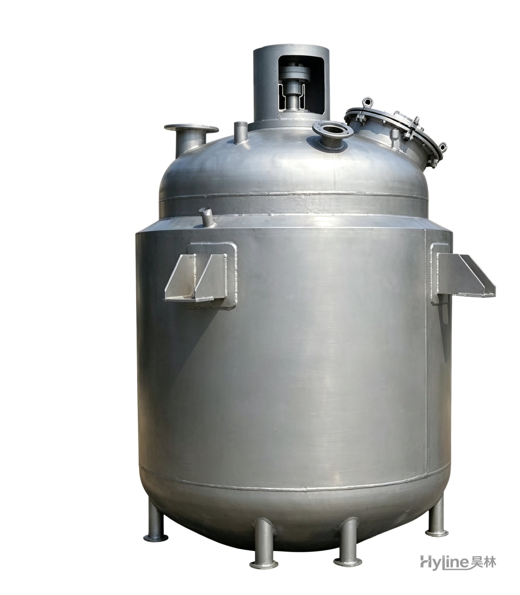
Jacketed Reactor
The typical main reaction vessel in chemical production. Mixing, heating and cooling disperse and mix materials for reaction and polymerization. The jacket circulates thermal oil/steam for heating or cooling water for temperature control.
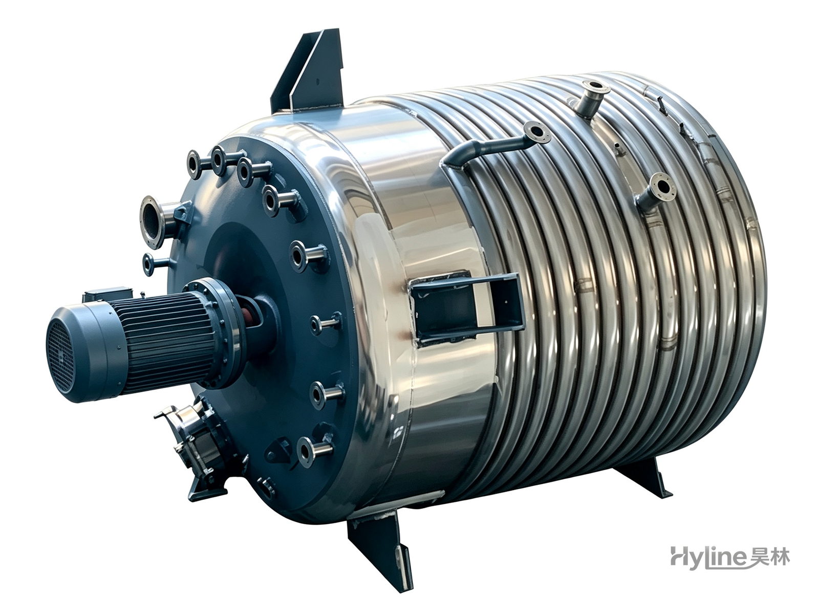
External Half-Coil Reactor
External half-pipe heating & cooling coils provide uniform, efficient heat exchange with zero material dead zones inside. Mirror-polished 304/316L stainless tank is clean and corrosion-resistant. For resin, new-energy slurry and pharmaceutical synthesis.
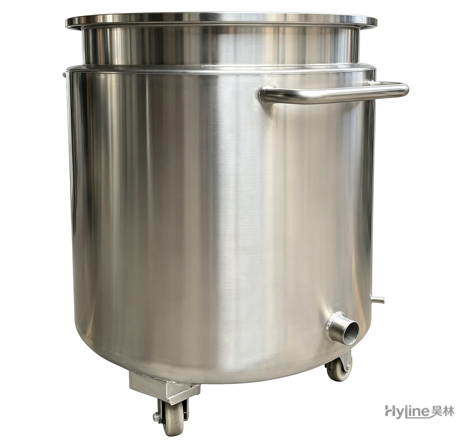
Stainless Steel Mixing Tank (Dispersion Drum)
Supporting vessel for dispersers and mixers in paints, coatings, adhesives, color slurries, inks and electronics. Available in 201/304 stainless with internal/external polishing and sloped bottom side discharge for complete draining.
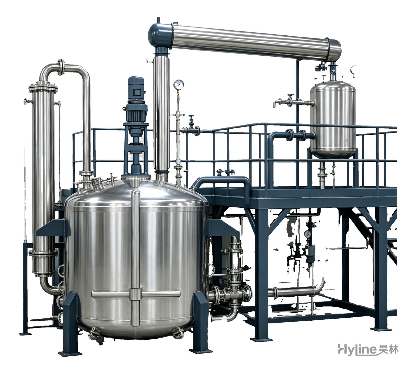
Complete Resin Production Equipment
Resin production packages built around the reactor, with vertical fractionating column, horizontal condenser and water separator for full synthesis, dehydration and reflux processes. Sizes from 300L to 30000L.
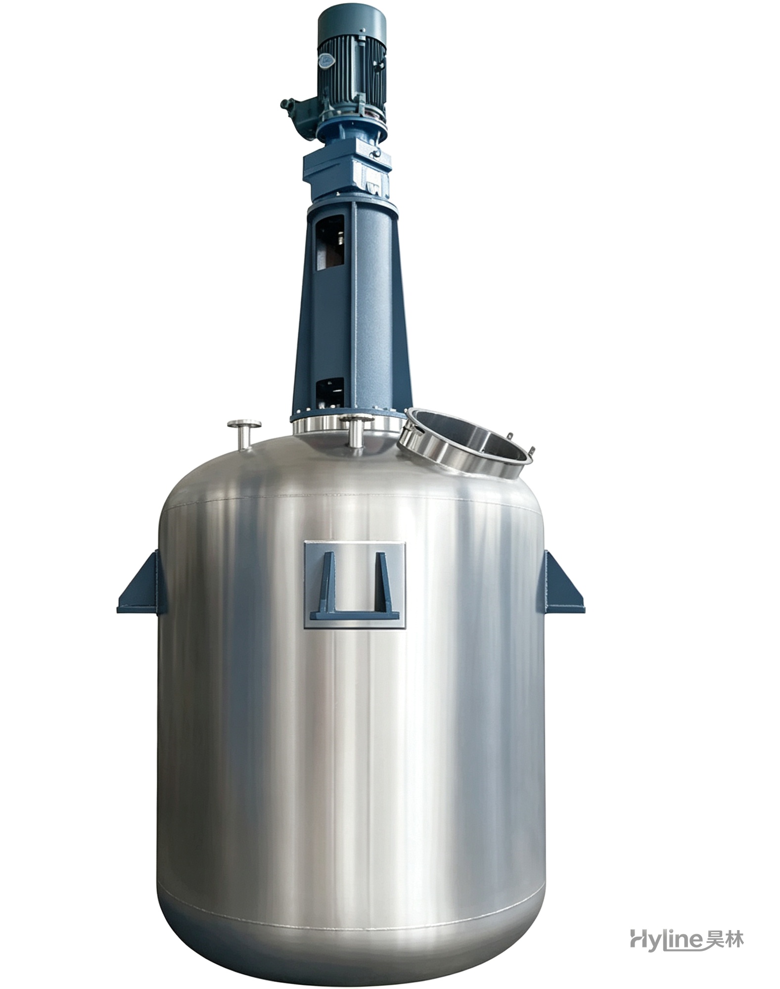
TC Series Mixing Kettle (Tinting)
For color matching in the paint industry and liquid-liquid / liquid-solid mixing in other industries. Uniform tinting, good miscibility, reasonable structure and powerful stirring.