
Why does the reactor agitator shaft vibrate? Critical speed, deflection and vibration control essentials
10/24/2026
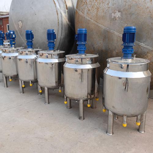
When a stainless steel reactor is running with a shaking agitator shaft, a leaking mechanical seal and periodic abnormal noise from the vessel, these are the most typical shaft-system failure signals of mixing equipment. Once the shaft shakes, the impeller may scrape the baffles or the internal coil, mixing quality deteriorates, seal wear accelerates, and in severe cases the shaft and coupling may suffer fatigue fracture, forcing the whole production line to stop. Many people react by changing the motor or adjusting the variable frequency drive, but in most cases the shaking of a long agitator shaft comes from the critical speed and deflection not being properly checked during design. This article explains why the agitator shaft shakes, how to check the critical speed and deflection, and how to control vibration of long shafts, helping you judge whether existing equipment is safe and which figures to put into the technical agreement when selecting new equipment.
Why does the reactor agitator shaft shake?
One-sentence conclusion: when the rotating speed of a cantilever agitator shaft approaches or exceeds the first critical speed, resonance amplifies the shaft-end amplitude, which appears as shaking; the longer the shaft, the thinner the shaft diameter and the heavier the overhung load, the more prominent the problem.
The agitator shaft is a typical cantilever structure: one end is fixed to the frame and the reducer output, and the other end carries the impeller in overhang. During rotation the impeller is resisted by the liquid, and the shaft itself has mass eccentricity and assembly errors, producing periodic exciting force. When the speed approaches the natural frequency of the shaft system, the exciting frequency coincides with the natural frequency and the amplitude is amplified by resonance, and the shaft-end swing increases markedly, which is the direct source of shaking. According to common experience in the chemical machinery industry, when the slenderness ratio of a cantilever agitator shaft (overhang length to shaft diameter) exceeds 25~30, critical speed and deflection checking is mandatory, and safety can no longer be inferred simply from a low speed. For high-viscosity materials and deep-liquid-level conditions, the actual load on the impeller is larger and the shaking risk rises further.
What is critical speed? What happens if the speed exceeds it?
One-sentence conclusion: the critical speed is the speed corresponding to the natural frequency of the agitator shaft system; once the operating speed exceeds the first critical speed, the shaft system enters the resonance zone, shaking intensifies and is hard to self-recover, so it must be avoided.
The critical speed of an agitator shaft is not a fixed value; it is determined by the shaft diameter, overhang length, impeller mass and support method. In engineering, the first natural frequency of the agitator shaft is converted into a speed, i.e. the first critical speed, usually denoted nc. According to common industry experience, the operating speed should normally be kept within 75% of the first critical speed to leave a speed margin. Above the first critical speed, the shaft runs in the resonance zone: a small fluctuation in liquid resistance multiplies the amplitude, and after passing the critical point new vibration modes appear, making the situation more complex. The closer the speed is to the critical speed, the larger the alternating load on the seal and bearings and the faster the leakage and wear, which is one of the main reasons for the high failure rate of long agitator shafts.
How to estimate the critical speed? When must it be checked?
One-sentence conclusion: the critical speed is estimated from the shaft diameter, overhang length and impeller load, and checking is mandatory when the overhang slenderness ratio exceeds 25~30 or the speed exceeds 150 r/min.
The critical speed is calculated by the equipment manufacturer during the design stage and written into the design documents. When making the technical agreement and pre-delivery acceptance, the user mainly checks whether the manufacturer provides the ratio of the operating speed to the critical speed. According to common industry experience, three figures can be used for preliminary judgment:
| Check parameter | Typical reference value | Note |
|---|---|---|
| Overhang slenderness ratio L/d | must check when above 25~30 | ratio of overhang length to shaft diameter, the longer the more dangerous |
| Operating speed / first critical speed | below 75% | leave a resonance margin, close to it means risk |
| Static deflection of shaft end | generally no more than 0.5mm or 1/2000 of shaft length, whichever is smaller | reflects shaft stiffness; thicken the shaft or add support if exceeded |
These three parameters should be clearly written into the technical agreement for reactors and mixing tanks. If the manufacturer cannot provide the critical speed check result, or the speed ratio exceeds 75%, it is recommended to require re-checking, or to thicken the shaft or add supports before finalizing the design.
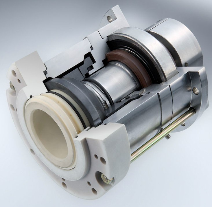
What does the deflection check calculate?
One-sentence conclusion: the deflection check calculates the maximum offset of the shaft end under the impeller self-weight and liquid resistance; excessive static deflection causes impeller scraping, seal misalignment wear and shaft system instability.
The deflection of the agitator shaft is determined by the shaft diameter, material, overhang length and overhung load. The shaft end carries the impeller and bears the liquid resistance during operation, so the shaft bends, and the offset of the shaft end is the static deflection. According to common industry experience, the static deflection of the shaft end is generally controlled within 0.5mm, or with 1/2000 of the shaft length as the upper limit, taking the smaller value as the allowable value. When the deflection is too large, the clearance between the impeller and the tank wall, baffles or internal coil is consumed, causing scraping and wear; the swing at the seal sleeve position increases, the sealing faces wear eccentrically, and leakage follows. For large-diameter reactors with a shaft length above 3 meters and deep-tank mixing conditions, the weight of the deflection check should be increased.
How to control the vibration of a long agitator shaft?
One-sentence conclusion: control the vibration of a long agitator shaft in five steps: first ensure the speed margin, then improve the shaft stiffness, then do impeller balancing and coupling alignment, and finally measure the vibration value during the trial run and fix the standard.
Step one: leave a speed margin in design, keeping the operating speed within 75% of the critical speed. Step two: improve the shaft stiffness; for an overlong cantilever, thicken the shaft, or add a bottom bearing at the tank bottom and an intermediate bearing at the middle section to turn the cantilever into a simply supported structure, which can significantly raise the first critical speed, according to common industry experience usually by 1.5~3 times. Step three: statically balance the impeller and arrange multiple impellers symmetrically to eliminate unbalanced torque. Step four: align the coupling during installation, keeping the alignment accuracy of the frame and reducer generally within 0.05mm to avoid additional bending moment. Step five: measure the vibration of the frame and shaft end with a vibration meter during the trial run; the equipment vibration velocity is generally controlled within 4.5mm/s (referring to below zone B of ISO 10816), and rework if exceeded. Once these five measures are implemented, the shaking problem of long agitator shafts can basically be eliminated.
When should a bottom bearing or intermediate support be added?
One-sentence conclusion: when the cantilever length exceeds 25~30 times the shaft diameter, or the working speed approaches 75% of the first critical speed, give priority to adding a bottom bearing or intermediate support to change the cantilever structure into two-point support.
The bottom bearing is installed on the vessel bottom or inside the bottom head, restraining the cantilever end of the agitator shaft, significantly raising the first critical speed and reducing both shaking and deflection together; the intermediate support is installed on the support plate in the upper-middle part of the vessel, suitable for deep-tank conditions with a large height-to-diameter ratio. According to common industry experience, the first critical speed can usually be increased by 1.5~3 times after adding a bottom bearing, but the bottom bearing is in the material liquid environment for a long time, so wear-resistant material and lubrication method must be selected by medium, and clearance and blockage protection should be considered for conditions with solid-containing liquids. Whether to add support is deduced backward from the critical speed check result: when the working speed approaches the 75% warning line of the critical speed, or the static deflection approaches the allowable value, the support scheme should be included in the design instead of waiting until a problem appears in the trial run.
How to troubleshoot excessive agitator shaft vibration?
One-sentence conclusion: troubleshoot excessive vibration in four steps — first verify the speed margin, then check the shaft-system clearance and bolts, then check the impeller balance, and finally check the material-liquid condition changes.
Step 1: verify the ratio of the actual working speed to the critical speed; when the speed margin is insufficient, give priority to adjusting the speed or adding support. Step 2: check whether the connecting bolts of the reducer output end, coupling and frame are loose, whether the bearing clearance has increased, and whether the runout of the shaft end and coupling exceeds tolerance; according to common industry experience, shaft-end runout exceeding 0.15mm needs treatment. Step 3: check whether the impeller is deformed, fouled or detached; fouling on the impeller surface destroys dynamic balance, and re-measurement is done after on-site cleaning. Step 4: verify whether the liquid viscosity, level and feeding method are consistent with the design condition; under high-viscosity and deep-liquid-level conditions, the impeller load increases by multiples. Following these four steps, most excessive vibration can be located and handled on site without replacing the whole shaft.
How to understand the input and output of shaft-system checking?
One-sentence conclusion: the shaft-system check takes four inputs — shaft diameter, span, impeller mass and speed — and outputs three results — static deflection, first critical speed and checking coefficient — which together determine the safety margin of the shaft system.
The equipment manufacturer performs shaft-system checking during design, and the buyer can judge the margin by understanding the three outputs. On the input side, the shaft diameter and span determine the stiffness, and the impeller mass and speed determine the excitation magnitude; on the output side, the static deflection reflects static deformation, generally controlled within 1/1000 of the shaft length, the first critical speed should be far away from the working speed, and the checking coefficient is the ratio of the critical speed to the working speed, taken above 1.3 according to common industry experience. Understanding this checking result makes it possible to judge whether the agitator shaft has enough safety margin under the target working condition, and also facilitates later communication with the manufacturer on design changes such as adding support or changing the shaft diameter.
Hyline Shengda produces stainless steel reactors and stainless steel mixing tanks and other mixing supporting equipment, supporting shaft-system configuration according to material viscosity, tank diameter and shaft length, as well as complete-line supporting design of planetary mixers and concentric twin-shaft mixers. Before making a mixing plan, it is recommended to fix the three parameters of material viscosity, tank diameter and speed range first, and then discuss the shaft system and impeller configuration.
Related reading: - How to maintain the reactor agitation system: assembly essentials of agitator shaft, mechanical seal and impeller - How to set the reactor agitation speed? Matching material viscosity, impeller type and linear speed
This article is compiled by Hyline Shengda Equipment Manufacturing Co., Ltd. (hyline.cn), mainly producing stainless steel reactors, mixing tanks, storage tanks, dispersers, concentrators and complete chemical lines, supporting non-standard customization.
Q&A from this article
Frequently asked questions and answers from this article
What if the long agitator shaft of a reactor shakes and the mechanical seal leaks? This article explains critical speed, deflection check and vibration control essentials to help you judge whether the shaft system is safe.
Related Products
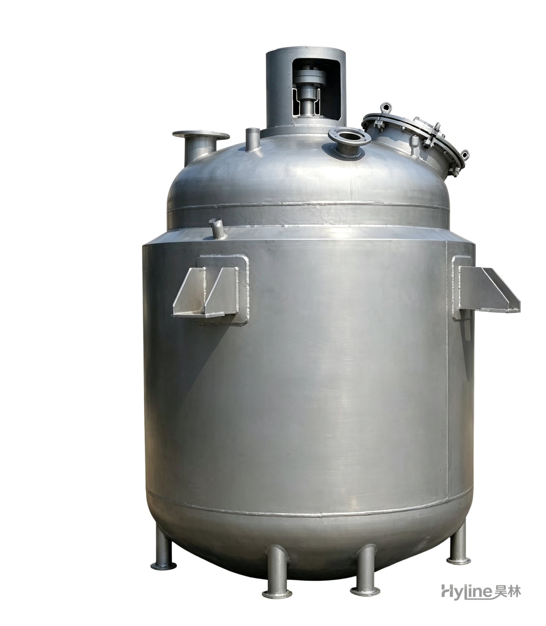
Jacketed Reactor
The typical main reaction vessel in chemical production. Mixing, heating and cooling disperse and mix materials for reaction and polymerization. The jacket circulates thermal oil/steam for heating or cooling water for temperature control.
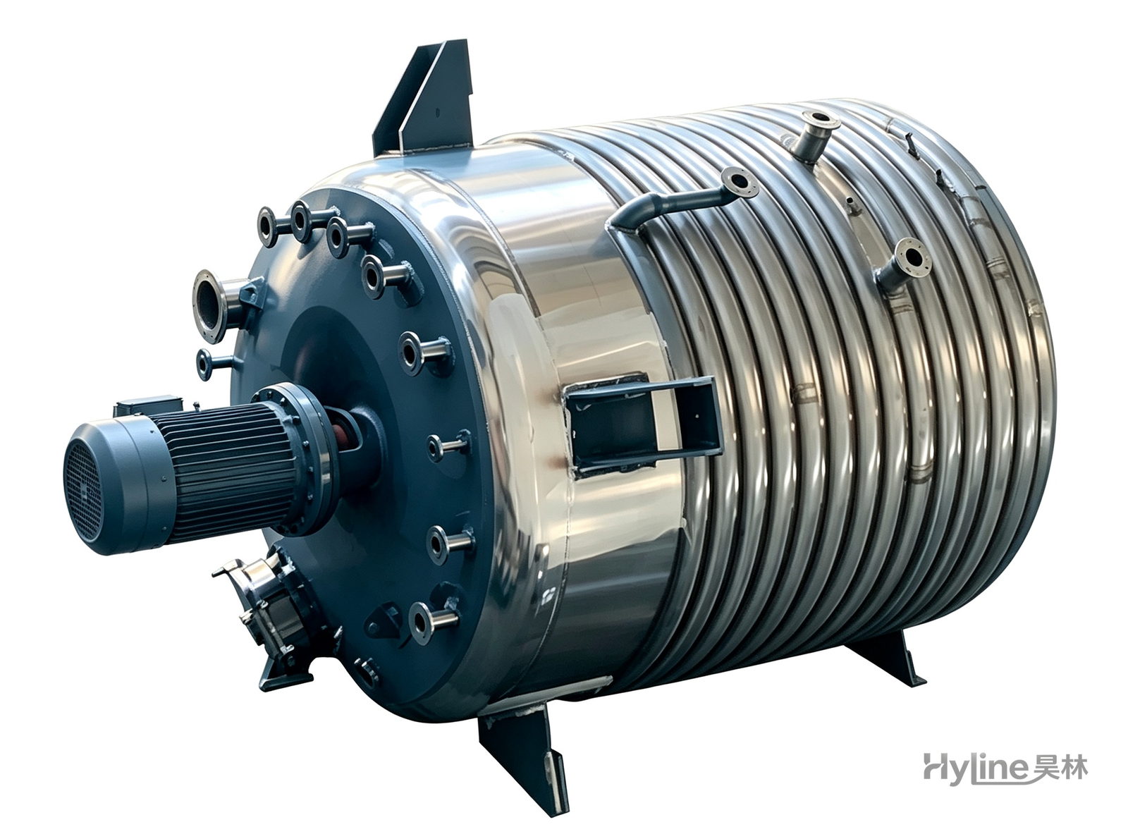
External Half-Coil Reactor
External half-pipe heating & cooling coils provide uniform, efficient heat exchange with zero material dead zones inside. Mirror-polished 304/316L stainless tank is clean and corrosion-resistant. For resin, new-energy slurry and pharmaceutical synthesis.
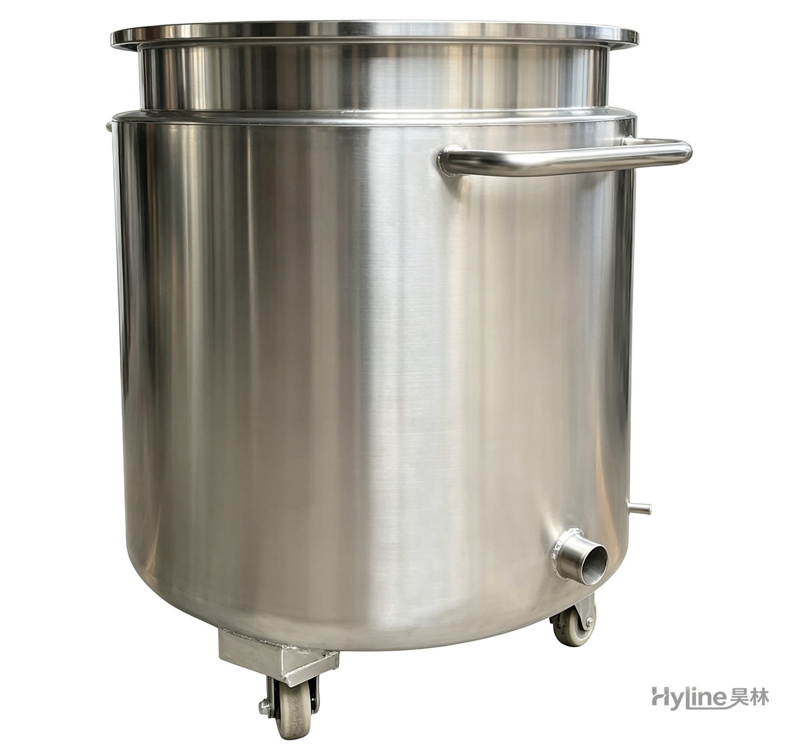
Stainless Steel Mixing Tank (Dispersion Drum)
Supporting vessel for dispersers and mixers in paints, coatings, adhesives, color slurries, inks and electronics. Available in 201/304 stainless with internal/external polishing and sloped bottom side discharge for complete draining.
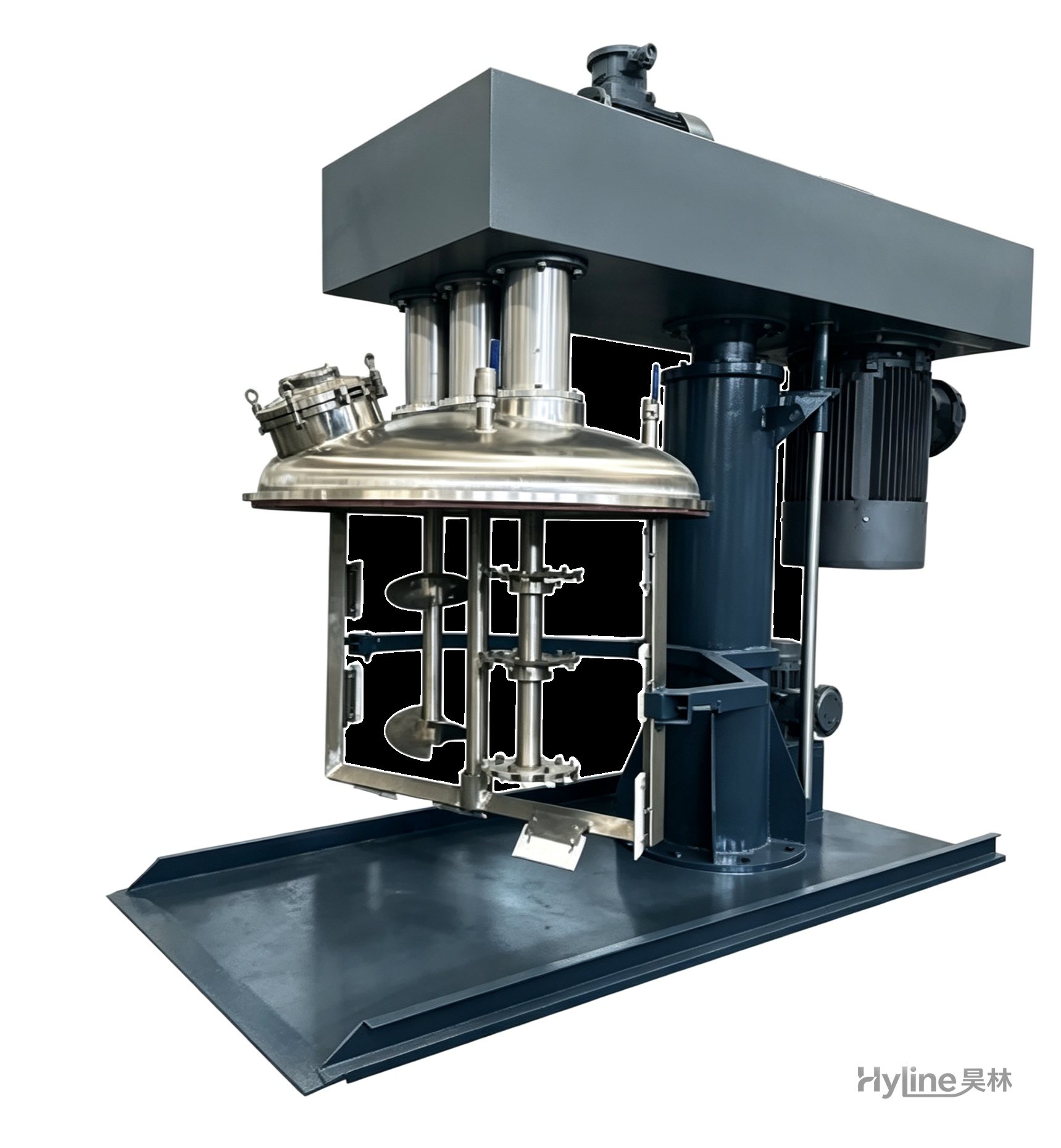
SJ Series Multi-Function Mixer
A new high-efficiency mixer for high-viscosity materials, rapidly dispersing, dissolving and homogenizing. Widely used in offset printing inks, putties and adhesives. Vacuum type customizable.
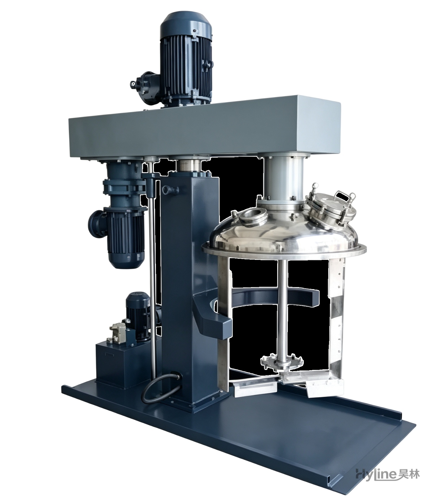
TSJ Series Concentric Twin-Shaft Mixer
Mixes materials of 3000-20000 cps. Low-speed blades with Teflon scrapers sweep the tank wall and push material to the center; high-speed toothed impellers disperse powerfully. High and low speeds run independently.