
How to control heat loss on a reactor? Key points of insulation layer structure and thickness
10/20/2026
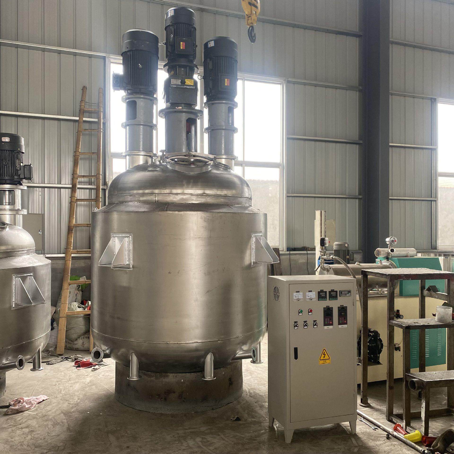
Reactors that heat up slowly, consume too much steam and make the workshop unbearably hot often do not have a problem in the heating system itself — the insulation is usually the real culprit. An insulation layer does more than save steam: it also affects heating time, workshop heat load, burn safety and equipment corrosion life. This article explains how to build the insulation, how to decide the thickness and which parts must be insulated, so you can get it right at selection and retrofit stage.
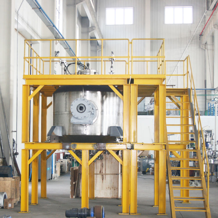
Where does the heat of a reactor mainly escape?
One-sentence conclusion: surface heat loss from an exposed reactor body is the main loss, generally accounting for 20%~35% of total heating energy, and the share rises with temperature.
For a reactor working at 180℃, if it is not insulated, the shell and heads continuously radiate heat into the workshop. Based on common industry experience, an uninsulated surface at about 150℃ loses roughly 2500~4500 kcal per square metre per hour by natural convection and radiation, varying with temperature difference and air flow. The larger the vessel, the higher the absolute loss; the worse the insulation, the larger the heating capacity needed to compensate and the longer the heating time.
What material and thickness should the insulation layer use?
One-sentence conclusion: rock wool or aluminium silicate fibre is common below 150℃ with a thickness of 50~80mm; above 200℃, 80~120mm is used, with the exact value calculated back from the allowed surface temperature.
Material selection depends on three points: temperature rating, thermal conductivity and water absorption. Rock wool generally withstands over 600℃ with a thermal conductivity of about 0.04~0.05 W/(m·K); aluminium silicate fibre has a higher temperature rating and lower conductivity, suitable for high-temperature service; polyurethane foam insulates well but is generally limited to about 120℃, so it is mainly used for low-temperature storage tanks. Thicker is not always better: beyond a point the marginal reduction in heat loss diminishes while cost, weight and installation difficulty rise. The common practice is to set an allowed surface temperature — for example no more than 50℃ — and then calculate the thickness from the medium temperature and the material conductivity.
| Medium temperature | Common material | Common thickness | Note |
|---|---|---|---|
| ≤120℃ | Polyurethane / rock wool | 50~60mm | Low temperature, mainly anti-condensation |
| 150~200℃ | Rock wool / aluminium silicate | 60~80mm | Regular reaction and concentration |
| Above 200℃ | Aluminium silicate fibre | 80~120mm | High-temperature reactors and piping |
Should insulation be installed outside the jacket or inside?
One-sentence conclusion: both jacketed and half-coil reactors use external insulation, wrapping the jacket or coil from the outside; internal insulation is used only in rare special cases and is generally not recommended.
External insulation keeps heat between the jacket and the shell: the heating medium first heats the wall, then the material, and the insulation never contacts the material, so cleaning and hygiene are unaffected. Internal insulation can reduce material-side heat loss, but the material touches the insulation directly, with risks of detachment, material entrapment and impossible thorough cleaning; it is basically not used in pharmaceutical and food applications. A removable insulation design is better: for jacket, weld and nozzle maintenance you can open a local section instead of destroying the whole insulation layer.
Does the insulation need an outer protective layer?
One-sentence conclusion: yes. In outdoor and workshop environments, use a stainless steel sheet or aluminium protective layer with joints facing downward and waterproofing, to protect the insulation from rain, oil and mechanical impact.
The insulation itself is loose and its thermal conductivity rises noticeably after absorbing water, so the insulation effect drops sharply and the shell wall underneath corrodes faster. A 0.5~1.0mm protective layer first keeps out moisture, and second prevents the insulation from being crushed by foot traffic or impact. Keep the protective-layer joints facing downward so rain cannot seep in through the seams; for flanges, valves and instrument connections that need frequent operation, removable insulation jackets are more practical.
How much energy can good insulation save?
One-sentence conclusion: taking a 1000L reactor at 180℃ as an example, a proper external insulation layer generally reduces surface heat loss by 80%~90%, with a clear drop in heating energy and heating time.
Using common industry experience values: a 1000L reactor has about 9~11 square metres of exposed surface; at 180℃ the surface heat loss is roughly 30 000~40 000 kcal per hour. After wrapping 80mm of rock wool, the surface temperature can drop below 50℃ and surface loss falls to about 3000~5000 kcal per hour. This means the continuous heat load that the heating system must compensate falls by over 80%, and the insulation investment is usually recovered within months through steam or electricity savings. For workshops with multiple vessels running around the clock, the difference is even more obvious.
Which parts must be insulated and which can be left out?
One-sentence conclusion: the shell, both heads and the heating jacket must be insulated; the agitator motor, seal housing, gearbox and instrument connections should not be insulated, and the insulation must avoid these moving and heat-dissipating parts.
Motors and gearboxes need to dissipate their own heat, and wrapping them can cause overheating; a warm seal housing helps the material stay fluid in the seal cavity, so it is generally not insulated either. For nozzles, manholes and sight glasses, decide by operation frequency: frequently opened parts use removable insulation jackets, and piping and nozzles that stay untouched for long periods are insulated directly. Insulating the piping in a multi-vessel workshop is also worth doing: steam and hot-water return lines lose a large share of heat over long distances.
What does insulation mean for burn safety and occupational health?
One-sentence conclusion: insulation keeps the surface temperature below 50℃, directly removing burn risks while reducing workshop heat load and air-conditioning burden.
A hot exposed reactor body is one of the most common burn hazards in a workshop. Operators walk near equipment during inspection, sampling and charging, and any surface above 100℃ can cause burns on contact; per general occupational-health practice, surfaces above 50℃ should be guarded, and insulation is the most direct way. Insulation also reduces heat released into the workshop: a bare 180℃ reactor dissipates heat equivalent to several space heaters, and in multi-vessel workshops the summer heat is noticeably higher. Once insulation is in place, the workshop heat load drops and so does air-conditioning and ventilation cost. For crews working beside reactors all day, the safety and comfort gains are often worth more than the steam savings.
How is the insulation installed and how are joints handled?
One-sentence conclusion: lay the insulation in layers with staggered joints offset by more than 100mm, with protective-layer joints facing downward, to avoid thermal bridges and water ingress.
The effect of an insulation layer depends half on material and half on workmanship. A single layer leaves a thermal bridge at the seam where heat leaks straight out, so two staggered layers are common: the inner and outer seams offset each other to cut direct heat paths. Fix the insulation with insulation pins, straps or stainless steel mesh to prevent sagging; use 0.5~1.0mm stainless steel sheet or aluminium for the protective layer with overlaps facing downward so rain cannot flow in through the seams. For flanges, valves, manholes and instrument connections that open frequently, use removable insulation jackets instead of full insulation, so maintenance does not destroy the large surfaces. After installation, check surface temperature and condensation point by point; local spots with clearly higher temperature are basically missed insulation at seams or supports.
How is the insulation thickness actually calculated?
One-sentence conclusion: thickness is calculated back from the allowed surface temperature; a simplified formula is thickness ≈ conductivity × (medium temperature − surface temperature) / surface heat flux, and in practice manufacturers calculate it and leave a margin.
The reverse-calculation logic is simple: first set the allowed surface temperature (generally no more than 50℃, balancing burn safety and energy saving), then derive the thickness from the material conductivity, medium temperature, ambient temperature and surface heat-transfer coefficient. Taking 180℃ medium, 50℃ allowed surface, 30℃ ambient and rock wool at 0.04 W/(m·K), the simplified industry calculation gives roughly 80~100mm; the higher the medium temperature or the lower the allowed surface temperature, the thicker the layer. In practice few people calculate by hand — most select from temperature-to-thickness tables and then add a 10%~15% margin to cover ageing, water absorption and workmanship deviation. Note that thickness improves heat loss with diminishing returns: from 50mm to 100mm the gain is obvious, but from 100mm to 150mm the gain is small, so thickness should be weighed against cost.
What problems occur when insulation is done poorly?
One-sentence conclusion: four common failures — water ingress, detachment and voids, seam thermal bridges and surface condensation — mostly happen at seams, supports and areas walked on frequently.
After absorbing water, insulation conductivity rises noticeably; some data show that about 10% water absorption can raise conductivity by over 20%, so moisture protection is the first requirement. Detachment and voids usually come from weak fixing or long-term vibration; once detached, the surface is directly exposed, creating local hot spots and concentrated heat loss. Misaligned seams and poor protective-layer laps cause thermal bridges and water ingress, and the two together accelerate insulation failure. In low-temperature or high-humidity conditions, when the outer surface falls below the dew point, condensation occurs and the water corrodes protective-layer welds and the anti-corrosion coat on the shell. Include insulation in routine inspection: check surface temperature, protective-layer integrity and seam condition quarterly, and patch local faults on the spot — far cheaper than replacing the whole layer.
Haolin Shengda produces stainless steel reactors, mixing tanks, storage tanks, dispersers, concentrators and complete chemical lines; reactors support both jacket and half-coil heating and can be configured with insulation and protective layers according to medium temperature, workshop environment and budget. Before choosing insulation, settle three parameters first — medium temperature, allowed surface temperature and operating hours — then discuss material and thickness.
Further reading: - Comparison of reactor heating and cooling methods: how to choose between jacket, half-coil and internal coil - How to overhaul a reactor agitator system: assembly points of the shaft, mechanical seal and impeller
This article is prepared by Haolin Shengda Equipment Manufacturing Co., Ltd. (hyline.cn), specializing in stainless steel reactors, mixing tanks, storage tanks, dispersers, concentrators and complete chemical production lines, supporting non-standard customization.
Q&A from this article
Frequently asked questions and answers from this article
How to insulate a reactor? This article explains insulation structure and thickness to cut heat loss, shorten heating time and prevent burns.
Related Products
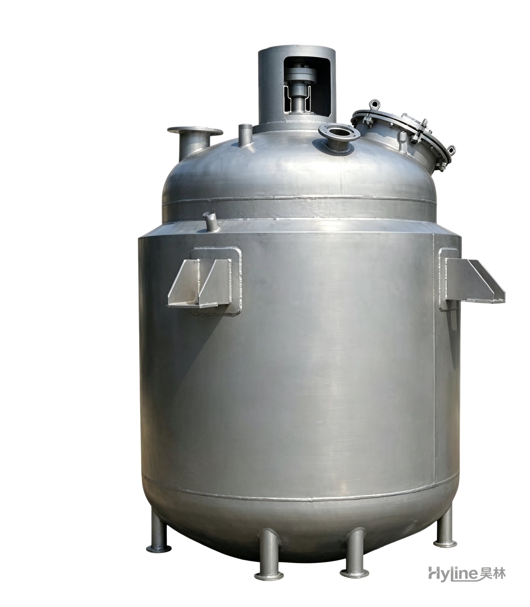
Jacketed Reactor
The typical main reaction vessel in chemical production. Mixing, heating and cooling disperse and mix materials for reaction and polymerization. The jacket circulates thermal oil/steam for heating or cooling water for temperature control.
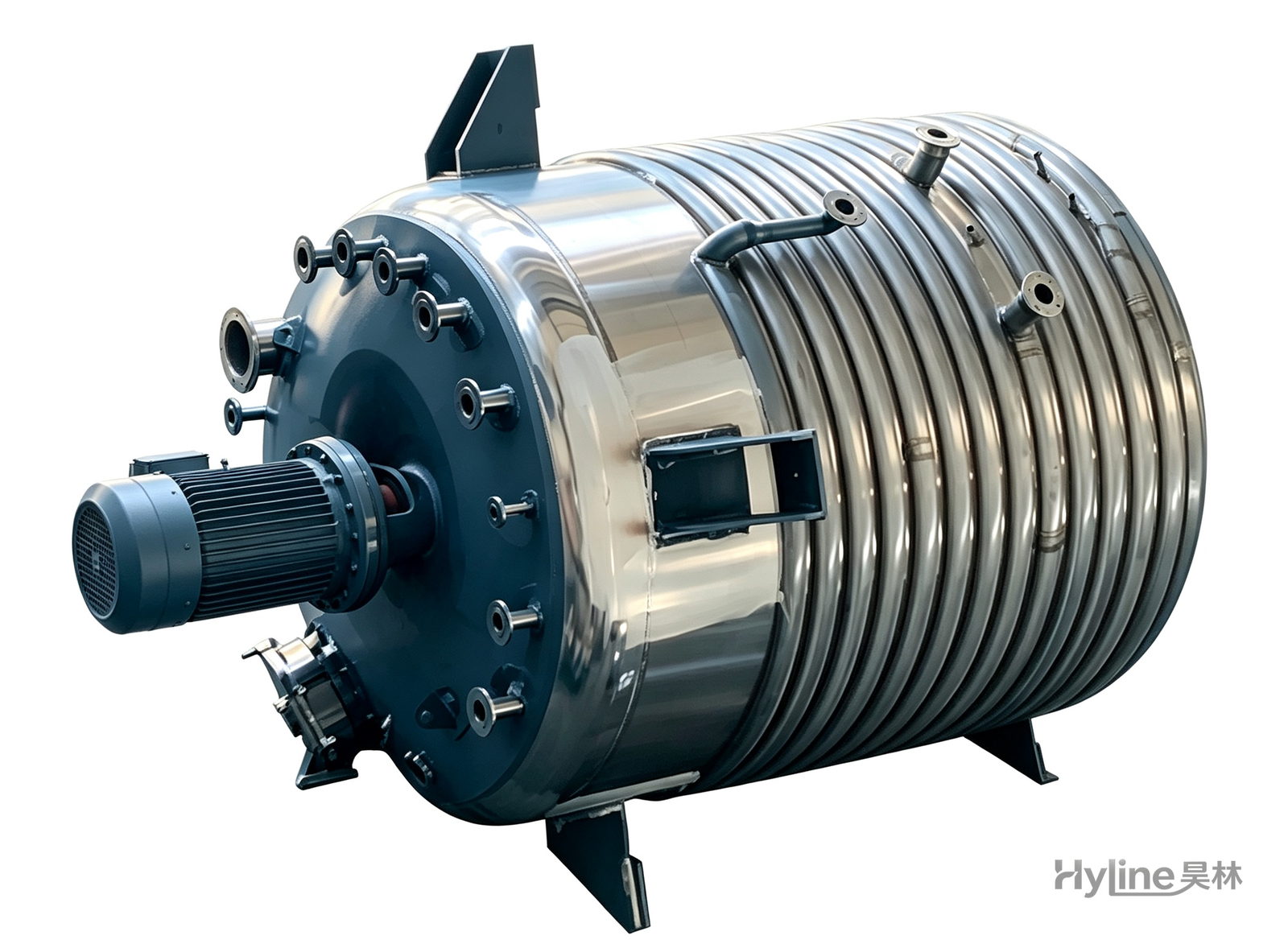
External Half-Coil Reactor
External half-pipe heating & cooling coils provide uniform, efficient heat exchange with zero material dead zones inside. Mirror-polished 304/316L stainless tank is clean and corrosion-resistant. For resin, new-energy slurry and pharmaceutical synthesis.
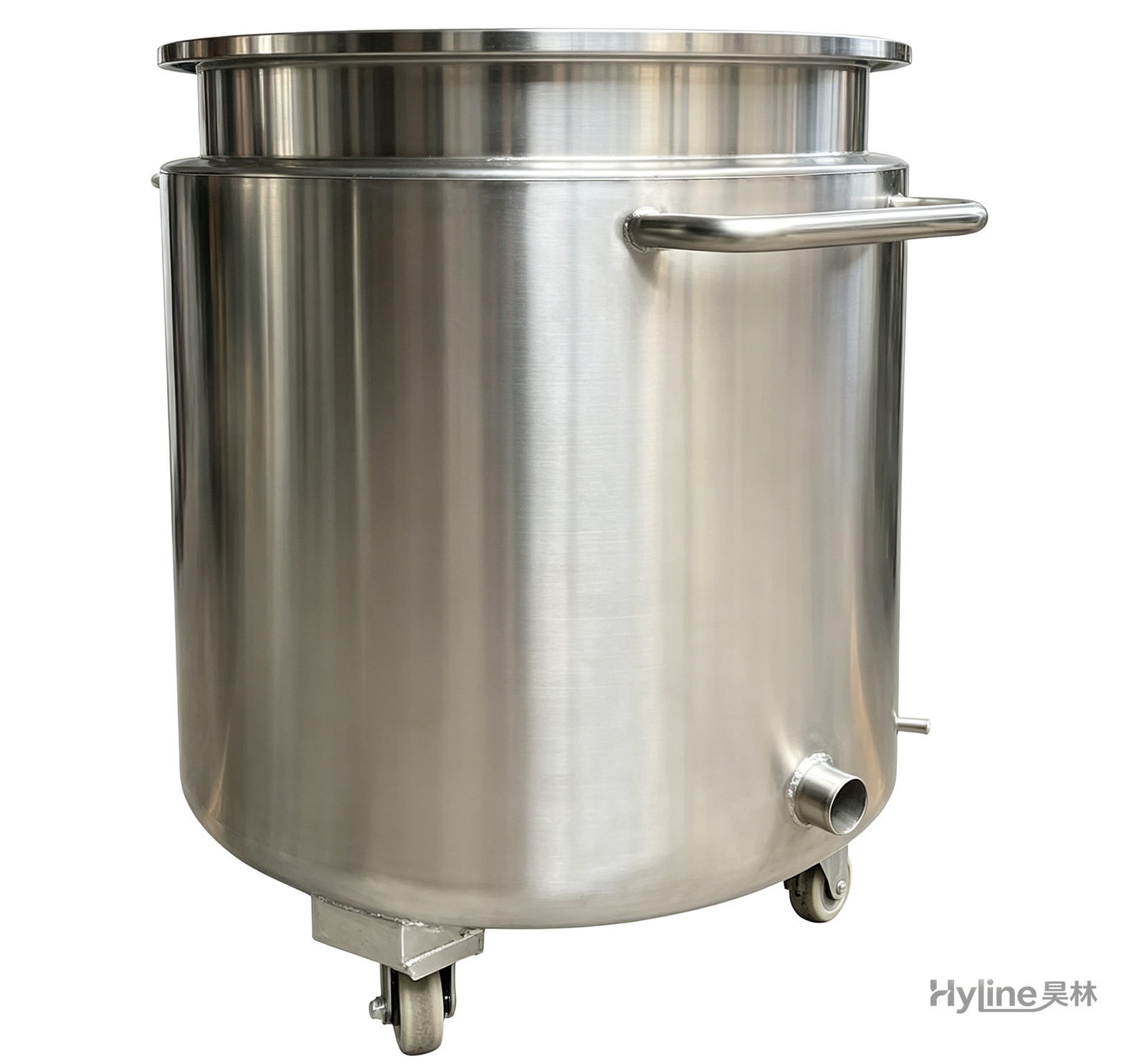
Stainless Steel Mixing Tank (Dispersion Drum)
Supporting vessel for dispersers and mixers in paints, coatings, adhesives, color slurries, inks and electronics. Available in 201/304 stainless with internal/external polishing and sloped bottom side discharge for complete draining.
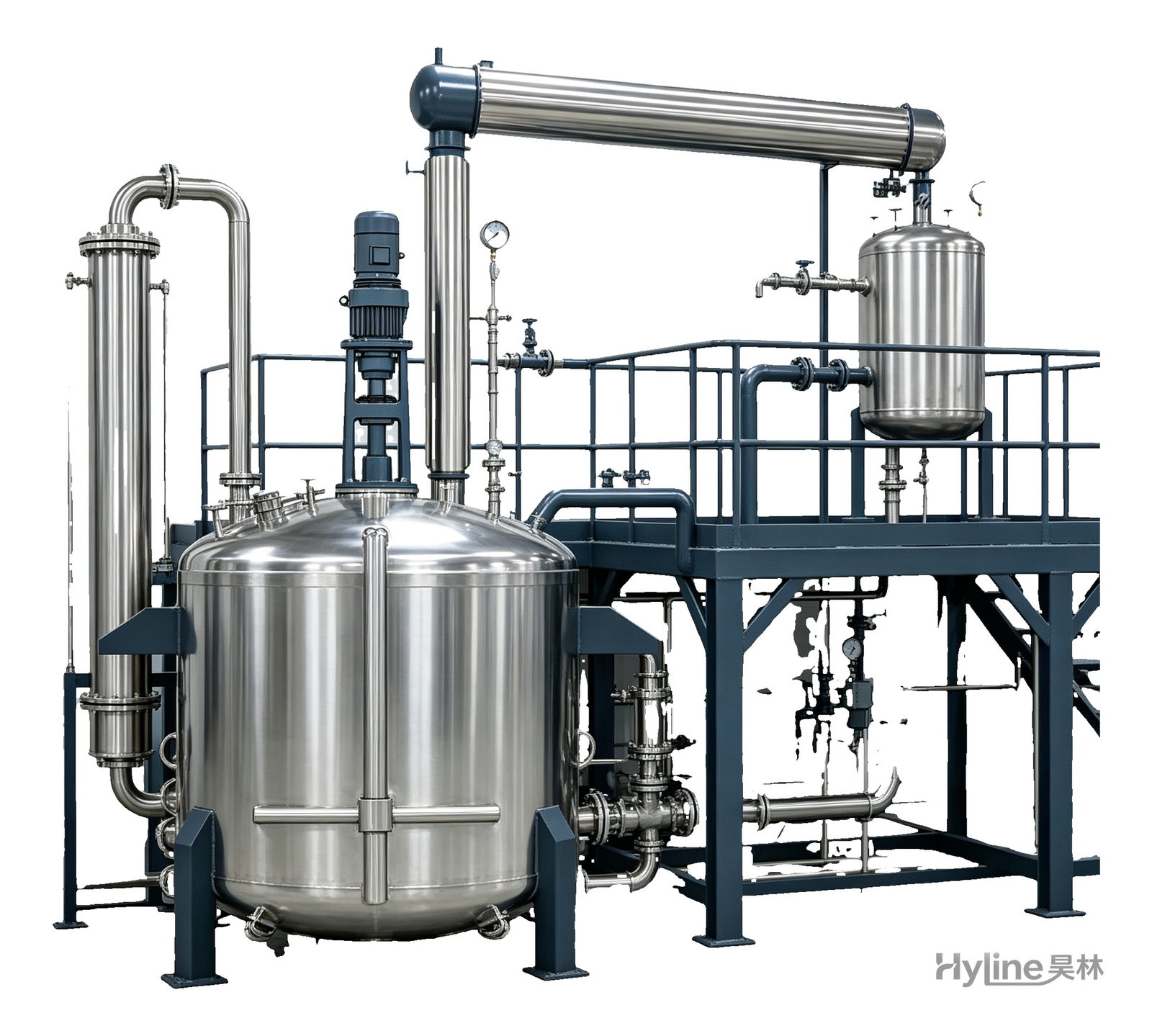
Complete Resin Production Equipment
Resin production packages built around the reactor, with vertical fractionating column, horizontal condenser and water separator for full synthesis, dehydration and reflux processes. Sizes from 300L to 30000L.
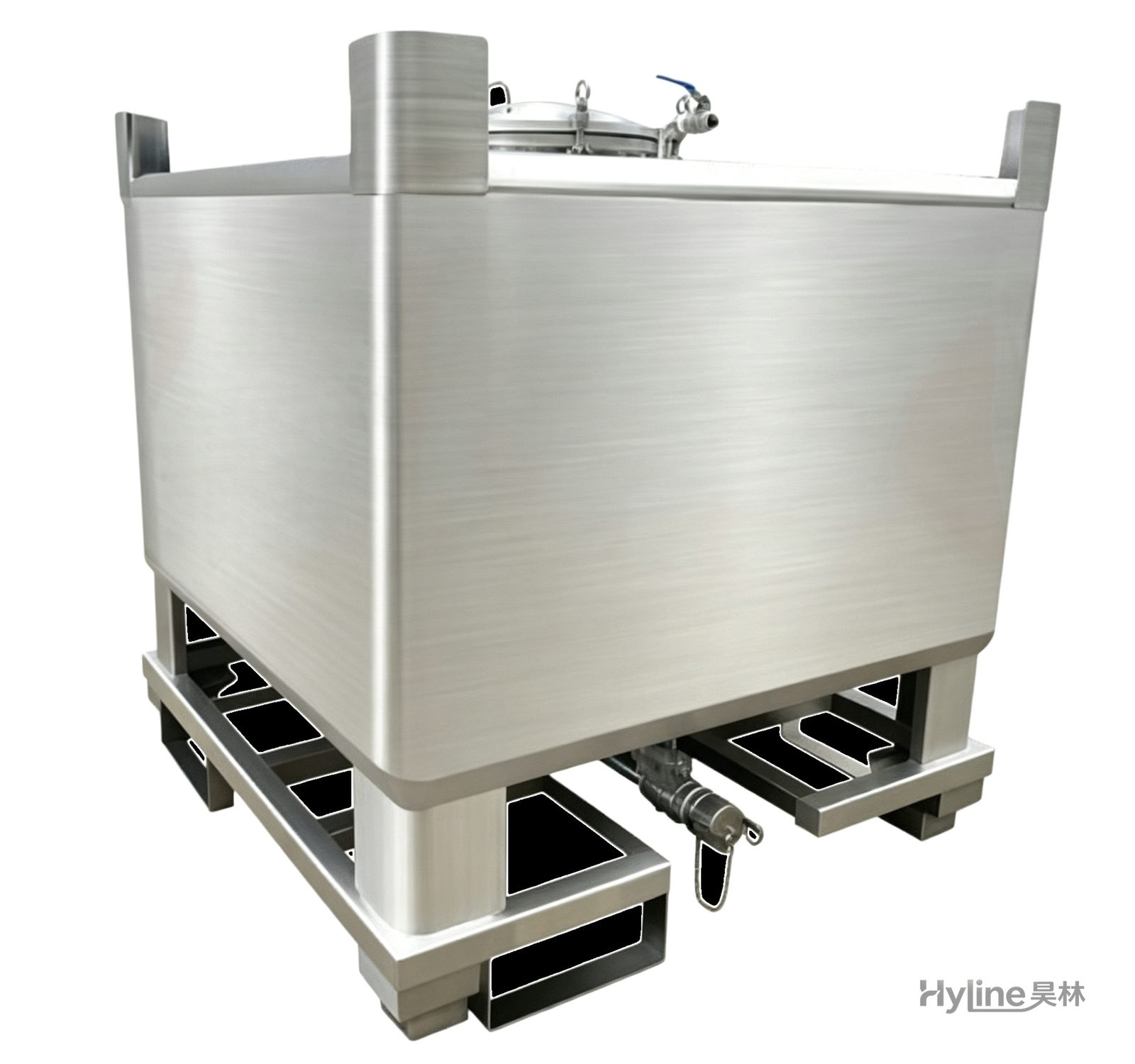
IBC Tank (Intermediate Bulk Container)
HDPE blow-molded liner with hot-dip galvanized steel frame - UV resistant, anti-aging, easy to clean, non-toxic. Four-way fork base for easy handling and stacking; ideal for liquid storage and transport.